
A storage device for automotive electronic equipment

A technology for electronic equipment and storage devices, applied in rack configuration, vehicle components, transportation and packaging, etc., can solve the problems of inability to realize electronic equipment visibility, storage, charging, blocking the driver's line of sight, and no clamping mechanism, etc. To achieve the effect of visual and storage functions

Inactive Publication Date: 2016-06-01
CHANGCHUN FAWAY ADIENT AUTOMOTIVE SYST CO LTD
View PDF5 Cites 0 Cited by
  • Summary
  • Abstract
  • Description
  • Claims
  • Application Information

AI Technical Summary

Problems solved by technology

[0002] In the automotive interior system, there is currently no electronic equipment management system integrated with the instrument panel, which cannot realize the functions of visualizing, storing, and charging electronic equipment. At present, drivers usually place their smartphones on the sub-panel, seat, or instrument panel. , and there is no clamping mechanism, the mobile phone is not within the driver's field of vision during driving (you cannot quickly find the mobile phone when making a call), and there is a risk of bumping the mobile phone during the braking and acceleration of the car. If you want to charge electronic devices , it is necessary to use a charging cable to connect the electronic device and the USB interface, and the charging cable leaks outside, which affects the quality; the electronic navigator is usually adsorbed on the windshield glass through a suction cup, which may block the driver's line of sight, and may fly out during a car collision. risk of injury

Method used


Image

  • A storage device for automotive electronic equipment
  • A storage device for automotive electronic equipment
  • A storage device for automotive electronic equipment

Examples


Embodiment Construction

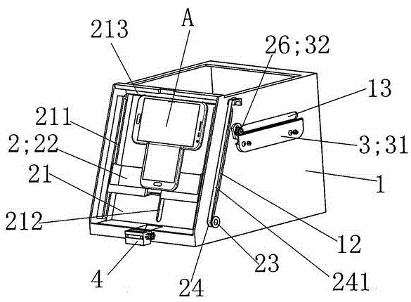
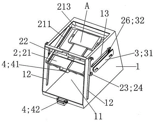
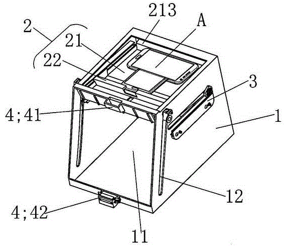
[0020] see figure 1 , figure 2 with image 3 As shown, this embodiment is composed of a box-type base 1, an electronic device clamping mechanism 2, a damper / rack mechanism 3 and a locking mechanism 4, as figure 1 , figure 2 , image 3 , Figure 4 with Figure 5 As shown, the electronic equipment clamping mechanism 2 is composed of a large bracket 21, a small bracket 22, two sliding columns 23, two first coil springs 24 and a second coil spring 25; the damper / rack mechanism 3 is composed of A rack 31 and a gear 32 are formed; the front side walls of the box-type base 1 are provided with a front chute 12, and the upper part of the side walls is provided with a rear chute 13, and the side walls of the box-type base 1 The rack 31 is arranged on the top, and the rack 31 is located below the rear chute 13. The two sides of the upper part of the large bracket 21 are provided with a gear shaft 26. The two gear shafts 26 are respectively located in the two rear chute 13 and can...


PUM


Abstract

The invention discloses a storing device for automotive electronic equipment. The storing device is composed of a box-type base, an electronic-equipment clamping mechanism, a damper / rack mechanism and a locking mechanism; the electronic-equipment clamping mechanism is composed of a large support, a small support and a power device; the small support is pulled down to have the electronic equipment clamped in an electronic-equipment clamping space formed between the small support and a block beam; when the electronic equipment is to be used, the large support of the electronic-equipment clamping mechanism is pulled down to the bottom of the box-type base, and the large support and the box-type base are locked by the locking mechanism; when the electronic equipment is to be concealed, the locking mechanism is pressed down, and the large support drives the small support and the clamped electronic equipment to be concealed in the box-type base. By the arrangement, the electronic equipment used in an automobile can be fixed and stored in a concealed manner, so that the electronic equipment cannot be bumped during braking and accelerating of the automobile; demands for clamping the electronic equipment of different models to be placed horizontally and vertically can be met by the aid of the clamping mechanism.

Description

technical field [0001] The invention relates to a vehicle-mounted device, in particular to a storage device of a vehicle-used electronic device. Background technique [0002] In the automotive interior system, there is currently no electronic equipment management system integrated with the instrument panel, which cannot realize the functions of visualizing, storing, and charging electronic equipment. At present, drivers usually place their smartphones on the sub-panel, seat, or instrument panel. , and there is no clamping mechanism, the mobile phone is not within the driver's field of vision during driving (you cannot quickly find the mobile phone when making a call), and there is a risk of bumping the mobile phone during the braking and acceleration of the car. If you want to charge electronic devices , it is necessary to use a charging cable to connect the electronic device and the USB interface, and the charging cable leaks outside, which affects the quality; the electron...

Claims


Application Information

Patent Timeline
Patent Type & Authority Patents(China)
IPC IPC(8): B60R11/02B60R7/08
Inventor 杨帆董娟张丽丽孟瑞雪赵世轩刘乃嘉李刚郭英爽
Owner CHANGCHUN FAWAY ADIENT AUTOMOTIVE SYST CO LTD
Learn More