
A portable generator set based on draw rod architecture

A generator set and pull rod technology, which is applied in the directions of engine components, machines/engines, mechanical equipment, etc., can solve the problems of laborious handling of generator sets, poor adaptability to road conditions, and easy collision with operators, and achieves portability and operation. The convenience is improved, the volume of the whole machine is reduced, and the effect of the operation interface is improved

Active Publication Date: 2019-01-04
SUZHOU YUANNENG DONGLI TECH CO LTD
View PDF12 Cites 0 Cited by
  • Summary
  • Abstract
  • Description
  • Claims
  • Application Information

AI Technical Summary

Problems solved by technology

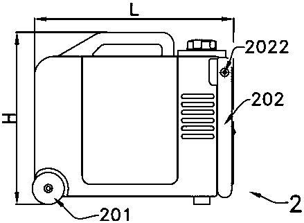
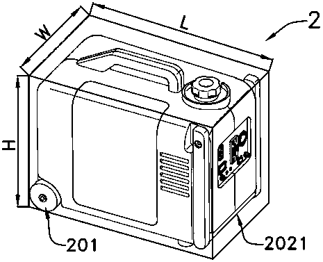
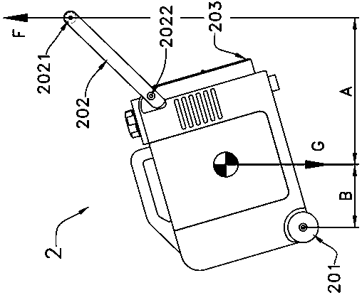
But this design has many problems, such as figure 2 As shown, when the operator lifts the front part of the generator set and drags the generator set 2 forward, since the generator set 2 is tilted backward (opposite to the forward direction), the P area 203 under the front part of the generator set is far away from the operator's feet It is very close to the legs, and it is easy to bump into the operator, which may cause injury in severe cases, which creates a great obstacle for the operator to quickly drag the generator set
Moreover, the action of the opening and retracting process of the rotary pull rod 202 is relatively complicated, the operation is not very convenient, and the efficiency is low.
On the other hand, in the process of dragging the generator set 2, the operator must always use an upward force F to overcome the weight G of the generator set to lift the front part of the generator set. Since the length L of the generator set 2 is relatively large (greater than the width W ), the distance B between the center of gravity of the generator set 2 and the center of the roller 201 in the horizontal direction is relatively large. , so F is relatively large, and it is still very laborious for the operator to carry the generator set 2
In addition, the two rollers 201 of the existing generator set 2 share one wheel shaft, and the wheel shaft running through the entire generator set 2 wastes the space inside the casing, so only rollers with smaller diameters can be used. Large, the adaptability to road conditions is poor, and the passing capacity of the generator set during transportation is also poor

Method used


Image

  • A portable generator set based on draw rod architecture
  • A portable generator set based on draw rod architecture
  • A portable generator set based on draw rod architecture

Examples


Embodiment 1

[0055] Such as Figure 3a to Figure 19 As shown, the portable generator set 1 of the present invention is mainly composed of a motor 6, a generator 7, an inverter 11, a roller device 3, a pull rod device 4, a casing 5, and an electrical panel 10.

[0056] Such as Figure 12 and Figure 14 As shown, the engine 6 of the present embodiment is an inclined cylinder engine, and the multistage permanent magnet generator 7 is arranged at the rear of the engine and is connected with the output end of the rear of the crankshaft of the engine, belonging to a post-mounted generator. Of course, the vertical cylinder engine can also be selected as required, and the front generator can be used to reduce the width W of the generator set. An inverter 11 is arranged at the front of the engine, and the inverter 11 is used to convert the intermediate frequency alternating current output by the multistage permanent magnet generator 7 into a power frequency alternating current with stable voltage...

Embodiment 2

[0086] Compared with the first embodiment, the main difference of the second embodiment is that the electrical panel 10 and the electrical box 506 are arranged on the right side 104 of the generator set.

[0087] Such as Figure 20 and Figure 21 As shown, the electrical panel 10 and the electrical box 506 of this embodiment are arranged on the right casing 502 between the two rod barrels 402 of the pull rod device 4 , and the electrical box 506 is connected to the right casing 502 . In this embodiment, the electrical panel 10, the starter handle 609, and the choke handle 611 are concentrated on the same side of the casing 5, which is beneficial to improve the operation convenience of the generator set.

Embodiment 3

[0089] Compared with embodiment one, the main difference of embodiment three is:

[0090] The casing 5 has different structures, such as Figure 22 to Figure 26 As shown, the casing 5 in this embodiment is composed of a left casing 501 and a right casing 502, without a separate lower casing, a maintenance cover 504 is arranged on the right casing 502, and the air inlet 505 of the generator set 1 It is also arranged on the right casing 502. Two damping feet 509 are arranged on the bottom of the left casing 501 and the right casing 502 respectively, and four foot pads 510 are arranged on the side of the left casing 501 .

[0091] The connection mode of engine 6 and casing 5 is different, as Figure 22 and Figure 26 As shown, the bottom of the engine 6 in this embodiment is provided with two connection holes in parallel, and a sleeve is arranged in the connection hole, and the sleeve and the connection hole are connected by a rubber sleeve for shock absorption, and one end of...


PUM


Abstract

A portable generator set based on a pull-rod framework. The generator set (1) is mainly composed of an engine (6), a generator (7) and a casing (5) and has a cuboid framework with length L, width W and height H. The engine (6) and the generator (7) are accommodated in the casing (5), and the engine (6) is connected with the casing (5) arranged at the bottom of the generator set. The left side face (103) or the right side face (104) formed by the length L and the width W in the cuboid framework of the generator set is provided with a pull type pull rod device (4), and the pull rod device (4) is vertically arranged along the height H direction of the generator set. By a series of adjustment and optimization designs, the generator set is more easy to move and can avoid bumping operators. Besides, space of the generator set can be utilized more reasonably, operation interface is improved, and portability and convenience in operation are greatly enhanced.

Description

technical field [0001] The invention relates to the technical field of portable generator sets, in particular to a portable inverter generator set based on a pull rod structure. Background technique [0002] The generator set is mainly composed of an engine, a generator and an electronic control system. It can convert the chemical energy of fuel into electrical energy. Backup power supply, mobile communication base station and many other occasions. [0003] Compared with the traditional power frequency synchronous generator set, the inverter generator set using multi-pole permanent magnet generator has the advantages of high efficiency, small size and light weight. Its weight and volume are only about 50% of the traditional generator set, which is truly reliable Realize "portable" generator set. [0004] However, the weight of the inverter generator set of about 2kw is generally more than 20kg, so it is still very inconvenient to carry and carry. Such as Figure 1a , Fi...

Claims


Application Information

Patent Timeline
Patent Type & Authority Patents(China)
IPC IPC(8): F02B63/04F02B77/00
CPCF02B63/04F02B77/00
Inventor 朱正华
Owner SUZHOU YUANNENG DONGLI TECH CO LTD
Learn More