Non-cooperative target docking mechanism of forked frame

A technology of non-cooperative target and docking mechanism, which is applied in the field of non-cooperative target docking mechanism to achieve the effect of reasonable design, high compression rate and shortened axial dimension

Active Publication Date: 2014-12-03
HARBIN INST OF TECH
View PDF4 Cites 18 Cited by
  • Summary
  • Abstract
  • Description
  • Claims
  • Application Information

AI Technical Summary

Problems solved by technology

[0004] The present invention aims to solve the problem that no docking mechanism can complete docking for spacecraft without standard docking interfaces in the existing docking of non-cooperative targets, and further provides a yoke non-cooperative target docking mechanism

Method used


Image

  • Non-cooperative target docking mechanism of forked frame
  • Non-cooperative target docking mechanism of forked frame
  • Non-cooperative target docking mechanism of forked frame

Examples


specific Embodiment approach 1

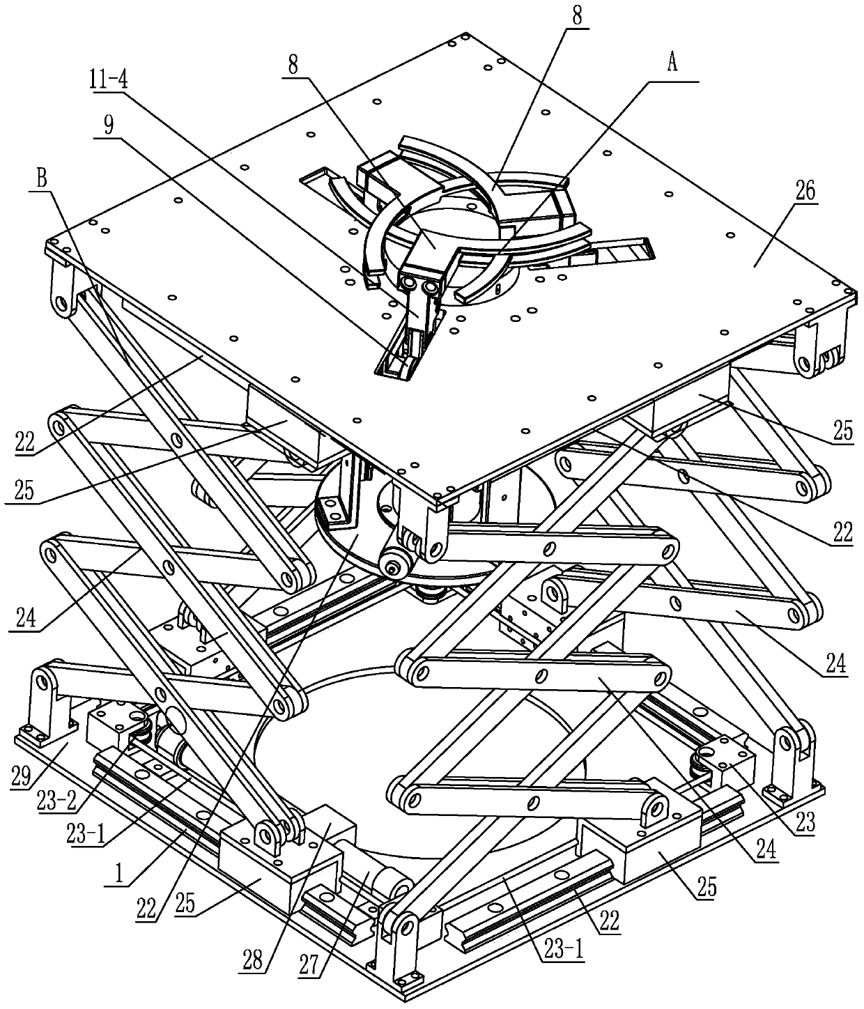
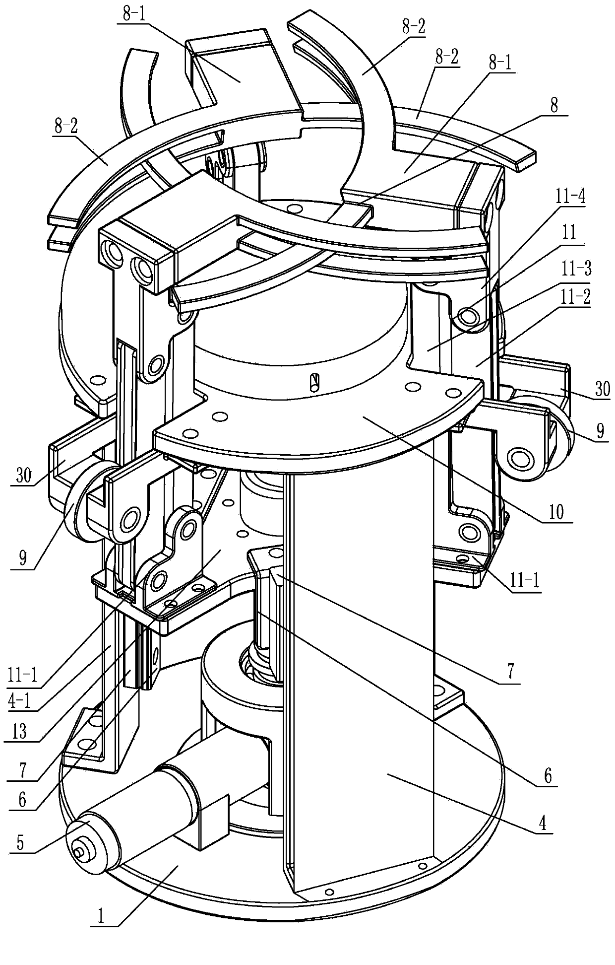
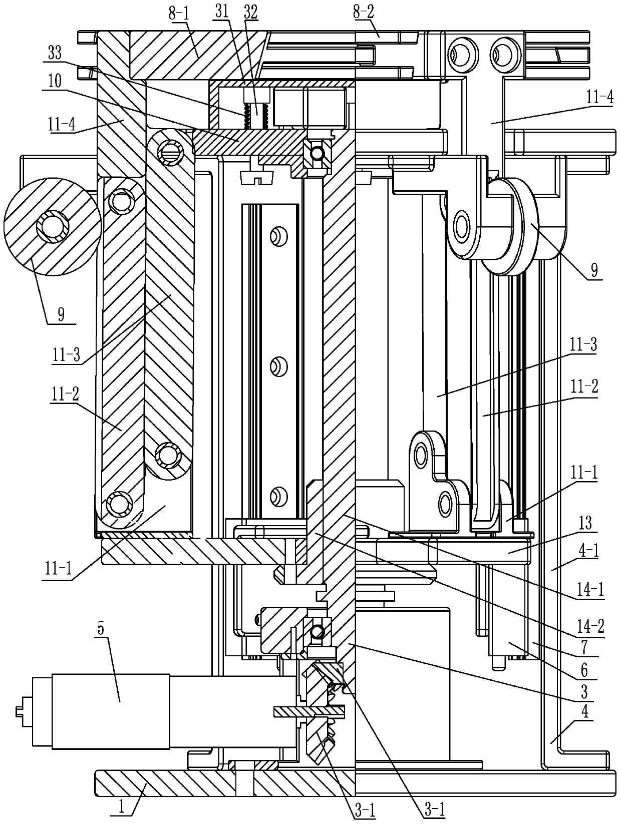
[0012] Specific implementation mode one: combine Figure 1-Figure 3 Explain that the non-cooperative target docking mechanism of the fork frame in this embodiment includes a catch mechanism A and a telescopic mechanism B; the catch mechanism A includes a base 1, a bevel gear pair 3, a slide rail bracket 4, a first motor 5, and an upper cover 10 , a support frame 13, a first lead screw pair 14, three terminal clamping claws 8, three first sliders 6, three first slide rails 7, three rollers 9 and three sets of four-bar linkage mechanisms 11;

[0013] The loam cake 10 is arranged on the top of the base 1, between the loam cake 10 and the base 1, a slide rail support 4 connected with the two is installed, three slide rails 7 are evenly distributed along the circumference of the loam cake 10 on the slide rail support 4, and the base 1 is installed with the first motor 5 axially arranged horizontally, one of the bevel gears 3-1 in the bevel gear pair 3 is arranged axially horizontal...

specific Embodiment approach 2

[0018] Specific implementation mode two: combination figure 2 and image 3 Note that the slide rail bracket 4 in this embodiment includes three support rods 4-1, and the three support rods 4-1 are evenly distributed along the circumference of the upper cover 10, and each support rod 4-1 is equipped with a slide rail 7. The three support rods 4-1 are connected to the upper cover 10 and the base 1 respectively. In this way, an enlarged space is formed between the three support rods, which facilitates the disassembly and assembly of the first lead screw pair, the bevel gear pair and the first motor. Others are the same as in the first embodiment.

specific Embodiment approach 3

[0019] Specific implementation mode three: combination figure 2 Note that the base 1 and the upper cover 10 in this embodiment are circular. Such arrangement takes up little space and is simple in structure. Others are the same as in the first or second embodiment.


PUM


Abstract

The invention relates to a non-cooperative target docking mechanism of a forked frame and solves the problem that during non-cooperative target docking in the prior art, no docking mechanism is capable of being docked with a spacecraft without standard docking ports. The non-cooperative target docking mechanism comprises a capture mechanism and a telescopic mechanism; the capture mechanism comprises a base, a bevel gear pair, a slide rail support, a first motor, an upper cover, a support, a first lead screw pair, three end gripper jaws, three first sliders, three first slide rails, three rotors and three four-connecting-rod mechanisms; the telescopic mechanism comprises a second motor, a second lead screw pair, an upper base, a lower base, four forked hinge supports and four slide components. The capture mechanism is disposed between the upper base and the lower base, the four-connecting-rod mechanisms penetrate the upper base, the end gripper jaws are arranged on the upper portion of the upper base, and the forked hinge supports and the slide components are circumferentially and uniformly distributed between the upper base and the lower base along the first lead screw pair. The non-cooperative target docking mechanism is applicable to docking of non-cooperative targets.

Description

technical field [0001] The invention relates to a non-cooperative target docking mechanism, which belongs to the field of aerospace technology. Background technique [0002] The rapid development of space technology has put forward new requirements and challenges for the research of spacecraft application technology. In order to expand the functions and application scope of spacecraft, various countries have carried out research on various space application technologies. Since the early 1960s, countries have launched research on space rendezvous and docking technology. The former Soviet Union and the United States first conducted a large number of space rendezvous and docking researches and successfully applied them in practice. Space rendezvous and docking can be divided into two types: cooperative target docking and non-cooperative target docking. At present, the technology of cooperative target docking is quite mature, and the cooperative target docking mechanisms put in...

Claims


Application Information

Patent Timeline
Patent Type & Authority Applications(China)
IPC IPC(8): B64G1/64
Inventor 李隆球周德开刘伟民邵广斌张广玉宋文平
Owner HARBIN INST OF TECH
Why Eureka
Try Eureka