Vertical conveyor

A technology of vertical conveyor and circular conveying, applied in the field of vertical conveyor, can solve the problems of high labor intensity, low efficiency, easy fatigue, etc., and achieve the effect of safe conveying operation, low efficiency and high transportation efficiency

Inactive Publication Date: 2014-12-03
蔡芳拨
View PDF12 Cites 8 Cited by
  • Summary
  • Abstract
  • Description
  • Claims
  • Application Information

AI Technical Summary

Problems solved by technology

[0002] In the prior art, it usually involves a large number of cargo lifting and transferring operations, such as the storage of goods from fishing boats, etc. When the existing fishing boats transport the cargo into the warehouse, the staff in the upper, middle and lower places usually manually transfer the cargo upwards The disadvantages of warehousing are: 1. Since the whole process is manually operated, the transportation process is intermittent and the efficiency is extremely low; 2. The labor is in a state of working up and down for a long time, which is labor-intensive and easy to fatigue; 3. A large amount of labor is required , increasing labor costs

Method used


Image

  • Vertical conveyor

Examples


Embodiment 1

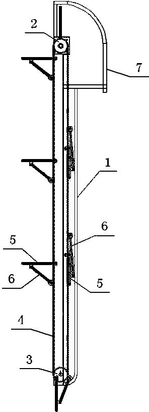
[0018] Embodiment 1: A vertical conveyor, including a frame body 1, on which a driving sprocket set 2 and a driven sprocket set 3 are arranged, and the driving sprocket set 2 is driven by a frequency conversion motor, The rotation speed and steering can be adjusted conveniently according to the needs. The driving sprocket set 2 is composed of two symmetrical coaxial driving sprockets on the left and right, and the driven sprocket set 3 is composed of two left and right symmetrical coaxial driving sprockets. The driving sprocket is composed of the driven sprocket, and the driving sprocket corresponds to the driven sprocket up and down. A matching transmission chain group 4 is arranged between the driving sprocket set 2 and the driven sprocket set 3, The transmission chain group 4 is composed of two symmetrical transmission chains on the left and right, each transmission chain is set on a set of corresponding driving sprockets and driven sprockets, and the two transmission chains...

Embodiment 2

[0021] Embodiment 2: In this embodiment, the driving sprocket set 2 is composed of three coaxial driving sprockets left, middle and right, and the driven sprocket set 3 is composed of three coaxial left, middle and right sprockets. The driven sprocket is formed, and the transmission chain group 4 is composed of three symmetrical transmission chains in the left, middle and right. Two adjacent transmission chains form a circular conveyor chain group, that is, the left and middle two transmission chains form the first circular conveyor chain group, and the middle and right transmission chains form the second circular conveyor chain group. The rest of the structure of this embodiment is the same as that of Embodiment 1. Compared with Embodiment 1, this embodiment has one more cycle conveyor chain group. Under the same working hours, its efficiency is twice that of Embodiment 1.

[0022] Of course, it can also be that the left, middle and right transmission chains form a circular c...


PUM


Abstract

The invention discloses a vertical conveyor comprising a frame body. A driving sprocket set and a driven sprocket set are disposed on the frame body. A transmission chain set is disposed between the driving sprocket set and the driven sprocket set. The transmission chain set is composed of transmission chains; each adjacent two of the transmission chains form a circulating conveyor chain set which a bracket is hinged to, a telescopic support is disposed on one side of the bracket, when the telescopic support is retracted, the bracket, the telescopic support and the circulating conveyor chain set form a triangular support platform, and when the telescopic support is extended, the bracket naturally droops. The vertical conveyor is capable of conveying cargoes continuously and vertically in two directions in a narrow cargo hatch and is high in conveying efficiency; the defects such that existing manual conveying causes low efficiency, ease of fatigue and high labor cost are overcome; conveying operation can be fast, efficient and safe.

Description

technical field [0001] The invention belongs to the field of transportation devices, and in particular relates to a vertical conveyor. Background technique [0002] In the prior art, it usually involves a large number of cargo lifting and transferring operations, such as the storage of goods from fishing boats, etc. When the existing fishing boats transport the cargo into the warehouse, the staff in the upper, middle and lower places usually manually transfer the cargo upwards The disadvantages of warehousing are: 1. Since the whole process is manually operated, the transportation process is intermittent and the efficiency is extremely low; 2. The labor is in a state of working up and down for a long time, which is labor-intensive and easy to fatigue; 3. A large amount of labor is required , increasing labor costs. Contents of the invention [0003] The technical problem to be solved by the present invention is to provide a vertical conveyor for the deficiencies of the ab...

Claims


Application Information

Patent Timeline
Patent Type & Authority Applications(China)
IPC IPC(8): B65G17/12B65G21/02B65G23/06
CPCY02P70/10
Inventor 蔡芳拨
Owner 蔡芳拨
Why Eureka
Try Eureka