A bathroom floor drainage anti-slip structure with a bathtub

A technology for bathtubs and bathrooms, which is applied in the field of drainage and anti-slip structures on the bathroom floor, which can solve the problems of not attracting attention, easy formation of water film, and easy fall, etc., and achieve the effect of improving the ability of preventing water accumulation, enhancing the anti-slip effect, and maintaining the anti-slip effect

Active Publication Date: 2017-01-18
QINGDAO HOUKE INFORMATION ENG
View PDF12 Cites 0 Cited by
  • Summary
  • Abstract
  • Description
  • Claims
  • Application Information

AI Technical Summary

Problems solved by technology

[0002] Existing shower rooms (except public bathrooms) are generally enclosed by glass or other materials in a corner of the toilet. There are two main reasons why people often slip and fall when taking a bath: one is that when the place and environment change, they are unconscious No attention has been paid, and the dynamics are as usual; the second is that the floor of the bathroom is smooth, and when the bathing water falls on the floor, a water film will be formed, especially after encountering soapy water and washing liquid water, the water film on the floor will be more slippery if it is difficult to dissipate
In order to discharge the water on the floor of the shower room in time, in addition to setting a floor drain near the wall on one side of the shower room, the side of the shower room without a floor drain should be higher than the side with a floor drain, so that the water on the floor of the shower room can flow to the floor drain and be discharged. In this way, the existing shower room still has the following defects: in the process of partitioning the bathroom, the joint between the partition and the ground often seeps, especially the treatment of the partition and the facade wall is often easily overlooked, even if the water seepage treatment is done, as time goes by Unintentional impact during use will also cause a large amount of bath water to seep through the floor and walls, while the existing shower room only has a drainage function, and the ability to prevent stagnant water is insufficient. Once the bath water is large, or the floor drain is blocked, it cannot be drained in time At this time, the entire floor of the shower room and the outside of the isolated bathroom are prone to water accumulation, and there are unsafe factors that are easy to fall
[0004] The Chinese utility model patent with the announcement number 202380527 discloses a bathroom drainage structure. The central plate of the drainage structure is a straight shallow groove, which has a certain anti-slip effect compared with the above-mentioned comparative document, but the straight strip Shallow grooved surfaces are still prone to water film formation, causing falls

Method used


Image

  • A bathroom floor drainage anti-slip structure with a bathtub
  • A bathroom floor drainage anti-slip structure with a bathtub
  • A bathroom floor drainage anti-slip structure with a bathtub

Examples


Embodiment 1

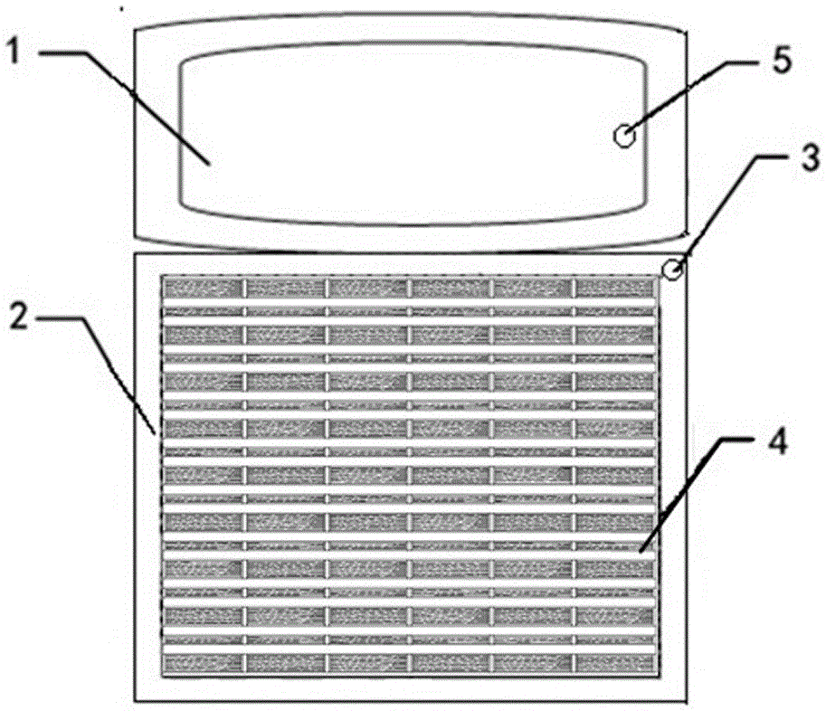
[0043] Such as figure 1 As shown, a bathroom floor drainage anti-slip structure with a bathtub includes a bathtub 1, and a drain hole 5 is arranged in the bathtub 1; an annular drainage ditch 2 is arranged outside the bathtub 1, and a floor drain 3 is arranged in the annular drainage ditch 2. The water overflowing from the bathtub 1 will flow into the annular gutter 2, and then flow to the floor drain 3 and be discharged to prevent the water from overflowing to the whole bathroom, which is beneficial to the drying of the floor in the bathroom. The positional relationship between the annular drainage ditch 2 and the bathtub 1 is relatively flexible, and this embodiment does not limit it, as long as the overflowing water from the bathtub 1 can flow into the annular drainage ditch 2 and be discharged, in this embodiment, the ring drainage ditch 2 One side is next to the bathtub 1.

[0044] The width of the annular drainage ditch 2 is about 50mm. If the annular drainage ditch 2 i...

Embodiment 2

[0046] The only difference between this embodiment and Embodiment 1 is that the positional relationship between the annular drainage ditch 2 and the bathtub 1 is different, and the annular drainage ditch 2 is also arranged around the bathroom.

[0047] Such as Figure 9As shown, the bathroom is provided with an annular drainage ditch 2 around, and the bathtub 1 is set in a corner of the bathroom. Shaped drain, this drain communicates with the annular drain 2, forming the annular drain 2 around the bathtub 1. The shape of bathtub 1 can be square, also can be designed into other any shapes, and present embodiment does not limit to this, as Figure 10 Shown, bathtub 1 is fan-shaped. Certainly, the placement position of the bathtub 1 in the bathroom can also be designed according to needs, which is not limited in this embodiment, as long as the annular drainage ditch 2 is correspondingly provided at the bathtub 1 . Such as Figure 11 As shown, the bathtub 1 can also be arrange...

Embodiment 3

[0049] The only difference between this embodiment and embodiment 1 or embodiment 2 is that the positional relationship between the floor drain 3 and the drain hole 5 is optimized. Such as Figure 12 with Figure 13 As shown, the floor drain 3 is connected to the floor drain sewer 6, the drain hole 5 is connected to the drain hole sewer 7, and the floor drain sewer 6 is connected to the drain hole sewer 7 obliquely at a certain angle. With such a design, when the drain hole 5 is blocked, the overflowing water can flow from the annular drainage ditch 2 to the floor drain 3, and then flow out from the floor drain sewer 6, thereby discharging the overflowing water.

[0050] When floor drain 3 is added, such as Figure 14 As shown, the additional floor drains 3 are respectively connected to the floor drain sewers 6, and the floor drain sewers 6 are respectively connected to the drain hole sewers 7 obliquely at a certain angle.


PUM


Abstract

The invention discloses a bathroom floor water-draining and slip-preventing structure with a bathtub. The bathroom floor water-draining and slip-preventing structure comprises the bathtub, a water draining hole is formed in the bathtub, an annular water draining ditch is arranged outside the bathtub, a floor drain is arranged in the annular water draining ditch, slip-preventing floor tiles are paved on a bathroom floor, each slip-preventing floor tile comprises a tile body, water draining grooves are formed in each tile body, each tile body is provided with napped slip-preventing portions which are arranged in a mode of 'one-wide and one-narrow' alternating, the surface of each napped slip-preventing portion is subjected to napping to be napped, shallow water grooves perpendicular to the corresponding water draining grooves are formed in the surface of each napped slip-preventing portion, and the slip-preventing floor tiles are paved on the bathroom floor in a manner of enabling the water draining grooves to uniformly face the floor drain. The bathroom floor water-draining and slip-preventing structure has high waterlogging-preventive capacity, can effectively drain water and prevent slip and is safe to use and convenient to clean.

Description

technical field [0001] The invention relates to drainage facilities, in particular to a bathroom floor drainage and anti-slip structure with a bathtub, which has the functions of timely drainage, anti-water accumulation, anti-slip, and convenient cleaning. Background technique [0002] Existing shower rooms (except public bathrooms) are generally enclosed by glass or other materials in a corner of the toilet. There are two main reasons why people often slip and fall when taking a bath: one is that when the place and environment change, they are unconscious No attention has been paid, and the dynamics are as usual; the second is that the floor of the bathroom is smooth, and when the bathing water falls on the floor, a water film will be formed, especially after encountering soapy water and washing liquid water, the water film on the floor will be difficult to dissipate and will be more slippery. In order to discharge the water on the floor of the shower room in time, in addit...

Claims


Application Information

Patent Timeline
Patent Type & Authority Patents(China)
IPC IPC(8): E04F15/02E03F5/04E03C1/20
Inventor 解思亮姜文程
Owner QINGDAO HOUKE INFORMATION ENG
Why Eureka
Try Eureka