Jet-flow reflection temperature field testing method

A test method and temperature field technology, applied in the field of high temperature and high speed fluid flow research, to reduce the number of drives, improve data accuracy, and save test costs

Active Publication Date: 2014-12-03
SHENYANG AIRCRAFT DESIGN INST AVIATION IND CORP OF CHINA
View PDF6 Cites 4 Cited by
  • Summary
  • Abstract
  • Description
  • Claims
  • Application Information

AI Technical Summary

Benefits of technology

This patented describes an improved measurement apparatus used during road construction or maintenance operations by optimizing the use of computerized numerical control (CNC). It uses advanced computing techniques such as fluid dynamics simulation software to predict how well different materials will behave under various conditions like heating or cooling cycles. By analyzing these simulations with CNC technology, engineers are able to creatively determine optimal material properties through optimized manufacture processes. Additionally, it includes multiple channels of acquiring samples from pipelines containing fluids at varying temperatures. Overall, this innovative solution helps improve efficiency and cost savings associated with road constructions and maintenance activities.

Problems solved by technology

This patented technical problem addressed by this patents relates to testing gas guards used at rocket launches or other applications where there are sudden changes caused by heated gases that can cause damage during flight time.

Method used


Image

  • Jet-flow reflection temperature field testing method
  • Jet-flow reflection temperature field testing method
  • Jet-flow reflection temperature field testing method

Examples


Embodiment Construction

[0023] The present invention will be further described below in conjunction with accompanying drawing and aero-engine jet reflection test implementation case:

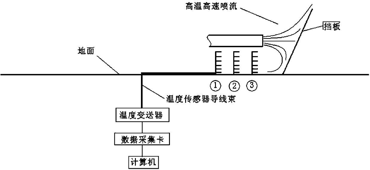
[0024] see figure 1 , is the functional block diagram of the test system. The velocity field test system consists of three sets of five-hole probes, scanning valves and data acquisition and recording systems. Each group of temperature measuring probes is installed on the soil-shaped test rake bracket according to the designed position.

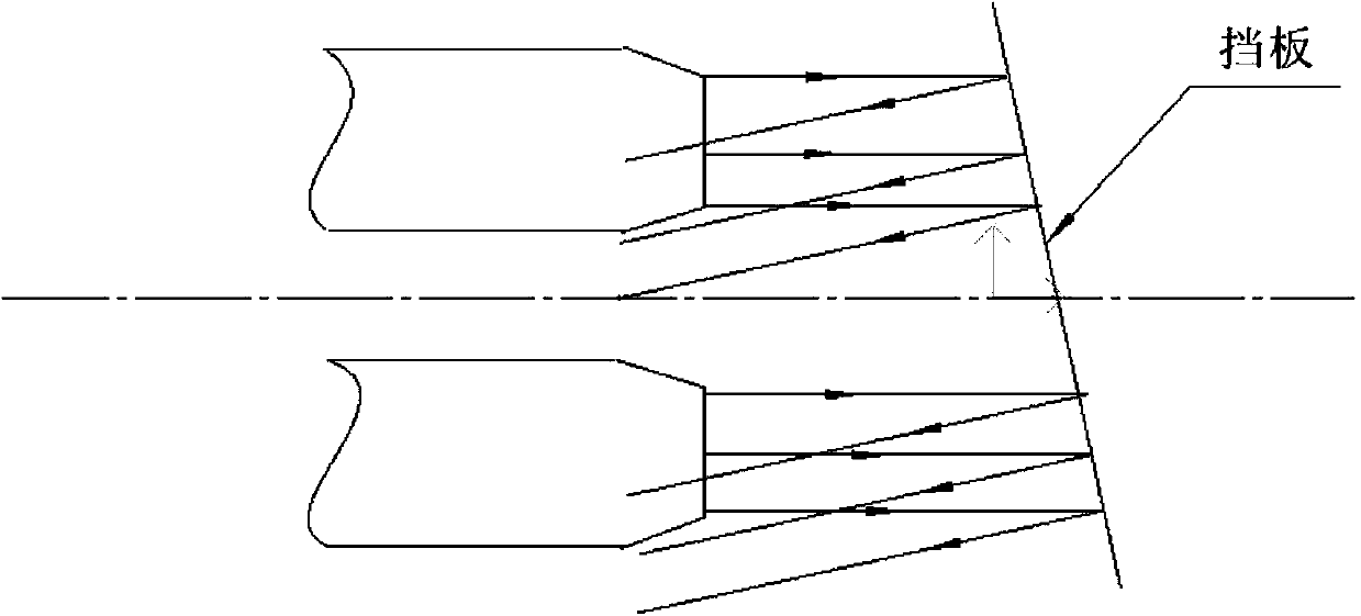
[0025] see figure 2 , is a schematic diagram of jet reflection under a 60° baffle. In the test, the size of the deflector is 3 × 6 meters, and the angle with the ground is 60°, and the angle with the plane of symmetry is 75°.

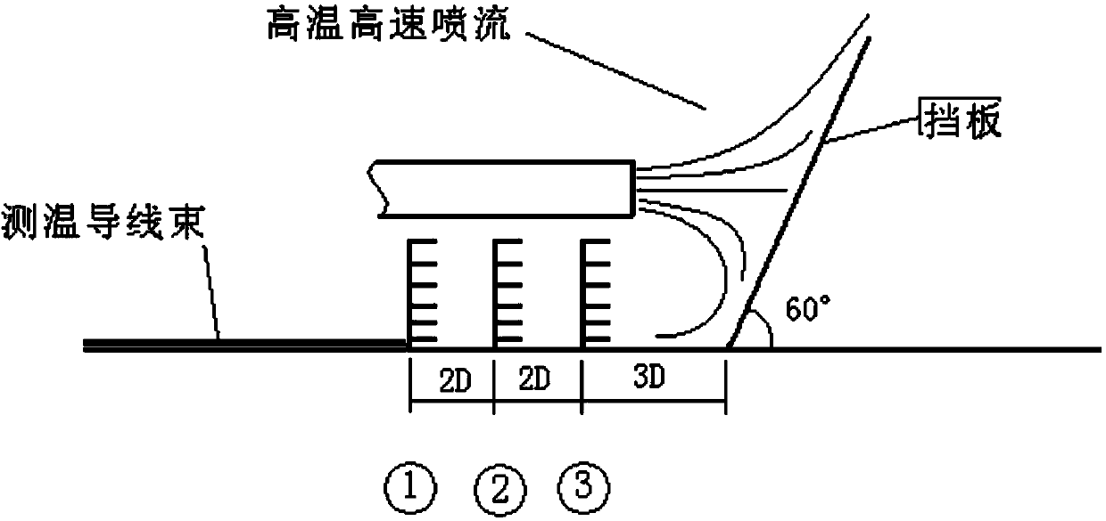
[0026] see image 3 , Schematic diagram of post-optimized rake arrangement. The baffle not only has a certain angle with the ground, but also deflects a certain angle with the symmetrical plane. Arranged as shown in the figure, the backflow of the left a...


PUM


Abstract

A jet-flow reflection temperature field testing method belongs to the field of research on flow of high-temperature high-speed fluids, and is applied to high-temperature high-speed jet flow. The method is characterized by comprising the steps of 1) preparing test equipment; 2) starting test when a system clock is synchronized with a jet flow generator; 3) processing data; and 4) implementing analysis and calculation. The method has the advantages that the amount of testing points, test data bulk and the number of test vehicles are decreased to a bearable scope of outfield; the ground of the outfield is not damaged, it is ensured that test targets are stable, and influence of outfield condensation and high-temperature on plastic pressure testing pipes are avoided; massive real-time high-frequency dynamic sampling data is collected in multiple channels and stored in a time-delay manner, the problems that the bandwidth and speed of a data collection and storage system are not high enough are solved, the data precision is solved, the operation frequency of jet flowing device is reduced, and the test cost is saved; the problem that test data is in one to one correspondence with jet flow state is solved; and a set of data collecting, processing and analyzing methods is thus established.

Description


Claims


Application Information

Patent Timeline
Owner SHENYANG AIRCRAFT DESIGN INST AVIATION IND CORP OF CHINA
Why Eureka
Try Eureka