A test method for jet reflection velocity field

A test method and reflection velocity technology, applied in the field of high-temperature and high-speed fluid flow research, to save test costs, solve the problem of insufficient system bandwidth and speed, and improve data accuracy

Active Publication Date: 2017-09-29
SHENYANG AIRCRAFT DESIGN INST AVIATION IND CORP OF CHINA
View PDF5 Cites 0 Cited by
  • Summary
  • Abstract
  • Description
  • Claims
  • Application Information

AI Technical Summary

Problems solved by technology

[0004] Solve the test problem of high-temperature high-speed jet flow meeting the baffle to generate jet reflection velocity field

Method used


Image

  • A test method for jet reflection velocity field
  • A test method for jet reflection velocity field
  • A test method for jet reflection velocity field

Examples


Embodiment Construction

[0034] The present invention will be further described below in conjunction with accompanying drawing and aero-engine jet reflection test implementation case:

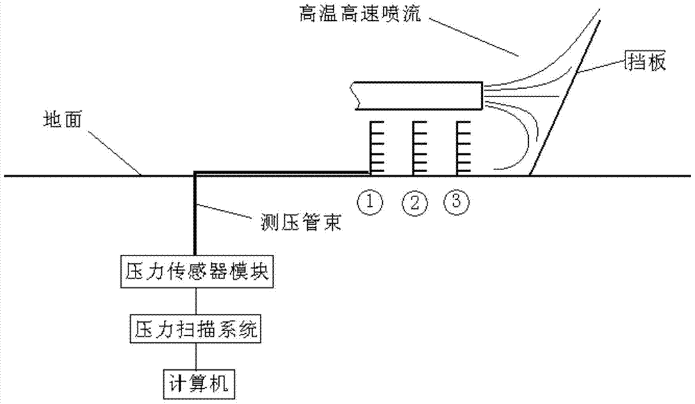
[0035] see figure 1 , is the functional block diagram of the test system. The velocity field test system consists of three sets of five-hole probes, scanning valves and data acquisition and recording systems. Each group of five-hole probes is installed on the soil-shaped test rake bracket according to the designed position.

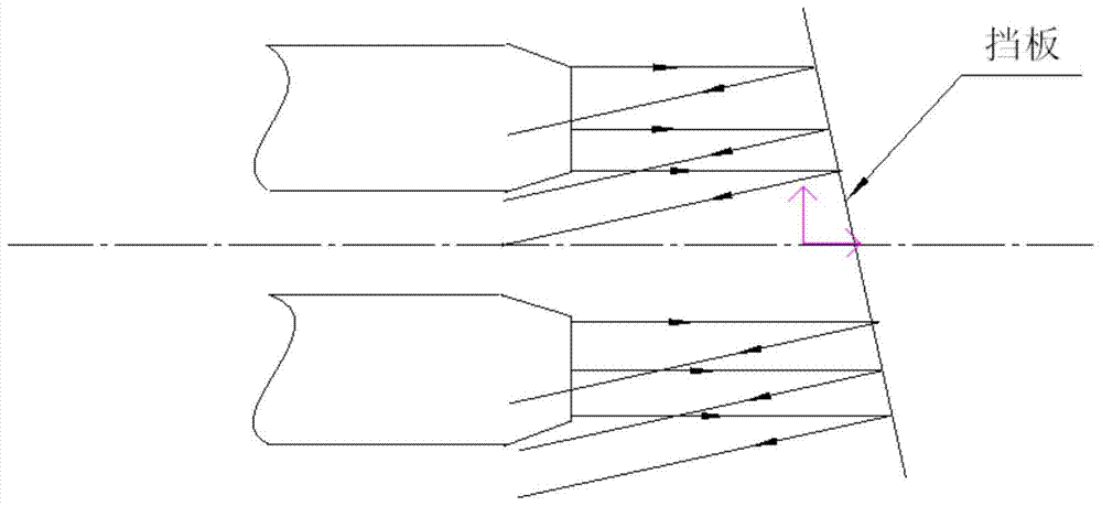
[0036] see figure 2 , is a schematic diagram of jet reflection under a 60° baffle. In the test, the size of the deflector is 3 × 6 meters, and the angle with the ground is 60°, and the angle with the plane of symmetry is 75°.

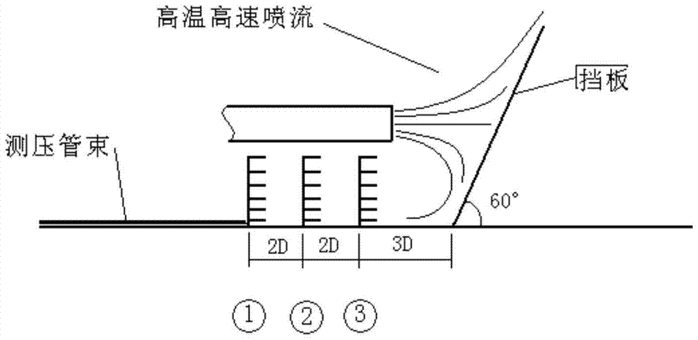
[0037] see image 3 , Schematic diagram of post-optimized rake arrangement. The baffle not only has a certain angle with the ground, but also deflects a certain angle with the symmetrical plane. Arranged as shown in the figure, the backflow of the left air inlet is ...


PUM


Abstract

The invention belongs to the research field of high-temperature and high-speed fluid flow, and in particular relates to a test method for high-temperature and high-speed jet reflection velocity field. It is characterized in that, firstly, measuring rakes for the shape of the processed soil; secondly, preparing test equipment; thirdly, starting the test after synchronizing the system clock with the jet flow generating device; fourthly, data processing; fifthly, analyzing and calculating. The advantages of the present invention are: the number of measuring points, the amount of test data and the number of test vehicles are reduced to the acceptable range of the outfield; the ground of the outfield is not damaged and the rake is stable, and the problem of condensation and high temperature in the outfield on the plastic pressure measuring tube is solved Impact: Multi-channel acquisition and delay transfer method is adopted for massive real-time high-frequency dynamic sampling data, which solves the problem of insufficient bandwidth and speed of data acquisition and storage systems, improves data accuracy, reduces the number of times the jet device is started, and saves test costs; solves the problem of testing One-to-one correspondence between data and jet flow status; a set of data acquisition, processing and analysis methods was established.

Description

technical field [0001] The invention belongs to the research field of high-temperature and high-speed fluid flow, and in particular relates to a test method for high-temperature and high-speed jet reflection velocity field. Background technique [0002] Gas rudders in rockets, binary nozzles of vector thrust engines, acetylene flame welding, iron and steel smelting, research on spray effects of dry powder fire extinguishers, etc. will encounter reflection problems of high temperature, high pressure, and high speed jets. The research on the test method of the high-temperature and high-speed reflection flow field has certain reference significance for the research of these problems. Contents of the invention [0003] The purpose of the present invention is: [0004] Solve the test problem of the jet reflection velocity field generated by the high-temperature high-speed jet encountering the baffle. [0005] Technical scheme of the present invention is: [0006] A jet refle...

Claims


Application Information

Patent Timeline
Patent Type & Authority Patents(China)
IPC IPC(8): G01M10/00
Inventor 潘英孟轩张立夫张召明
Owner SHENYANG AIRCRAFT DESIGN INST AVIATION IND CORP OF CHINA
Why Eureka
Try Eureka