Optimizing Method of Servo System Controller Based on Expected Closed-loop Transfer Function
A technology of transfer function and servo system, applied in the direction of total factory control, total factory control, electrical program control, etc., can solve problems that require experience, difficult system performance, low efficiency, etc., and achieve good performance results
- Summary
- Abstract
- Description
- Claims
- Application Information
AI Technical Summary
Problems solved by technology
Method used
Image
Examples
specific Embodiment approach 1
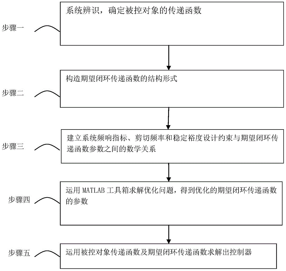
[0028] Embodiment 1: The servo system controller optimization method based on the expected closed-loop transfer function of this embodiment, combined with figure 2 Specifically, it is prepared according to the following steps:
[0029] Step 1: System identification, determine the transfer function of the controlled object;
[0030] Step 2. Construct the structural form of the desired closed-loop transfer function;
[0031] Step 3: Establish the mathematical relationship between the system frequency response index, shear frequency and stability margin constraints and the expected closed-loop transfer function parameters;
[0032] Step 4. Use the MATLAB toolbox to solve the optimization problem, and obtain the parameters of the optimized expected closed-loop transfer function;
[0033] Step 5: Use the controlled object transfer function and the expected closed-loop transfer function to solve the controller.
specific Embodiment approach 2
[0034] Embodiment 2: The difference between this embodiment and Embodiment 1 is that in the step 1, the transfer function of the controlled object is selected as In the formula, k G is the system gain, τ e is the electrical time constant, τ m is the electromechanical time constant, s is the Laplace operator;
[0035] The parameter k in the transfer function of the actual controlled object is measured by substituting the nominal parameter or parameter identification G , τe and τ m , so as to determine the transfer function of the controlled object.
specific Embodiment approach 3
[0036] Embodiment 3: The difference between this embodiment and Embodiment 1 or 2 is that the structural form of the desired closed-loop transfer function in the second step is: where Φ E (s) is the expected closed-loop transfer function constructed, ξ is the damping ratio, w n is the natural angular frequency, s is the Laplace operator, and T is the time constant of the auxiliary inertial link; among them, ξ and w n is the parameter to be optimized, and T is used to ensure the physical realizability of the controller, and it is taken as a constant value, usually less than w c is the cut frequency.
PUM
 Abstract
Description
Claims
Application Information
 - R&D
- Intellectual Property
- Life Sciences
- Materials
- Tech Scout
- Unparalleled Data Quality
- Higher Quality Content
- 60% Fewer Hallucinations
Browse by: Latest US Patents, China's latest patents, Technical Efficacy Thesaurus, Application Domain, Technology Topic, Popular Technical Reports.
© 2025 PatSnap. All rights reserved.Legal|Privacy policy|Modern Slavery Act Transparency Statement|Sitemap|About US| Contact US: help@patsnap.com


