Pre-stress lining design method for shield tunnel

Inactive Publication Date: 2009-02-11
TONGJI UNIV
View PDF3 Cites 17 Cited by
  • Summary
  • Abstract
  • Description
  • Claims
  • Application Information

AI Technical Summary

Problems solved by technology

[0007] At present, the application of prestressed lining of shield tunnels in Japan is based on structural tests; domestic research on prestressed lining

Method used


Image

  • Pre-stress lining design method for shield tunnel
  • Pre-stress lining design method for shield tunnel
  • Pre-stress lining design method for shield tunnel

Examples


Embodiment Construction

[0029] Before designing, several key issues in the design of prestressed lining of shield tunnels should be solved first:

[0030] 1. Calculation of opening angle of prestressed lining joints

[0031] The opening angle calculation of prestressed lining joints can be carried out according to the following formula:

[0032] 1 4 E c ′ bxθ - T p - E p A p Δ l ...


PUM


Abstract

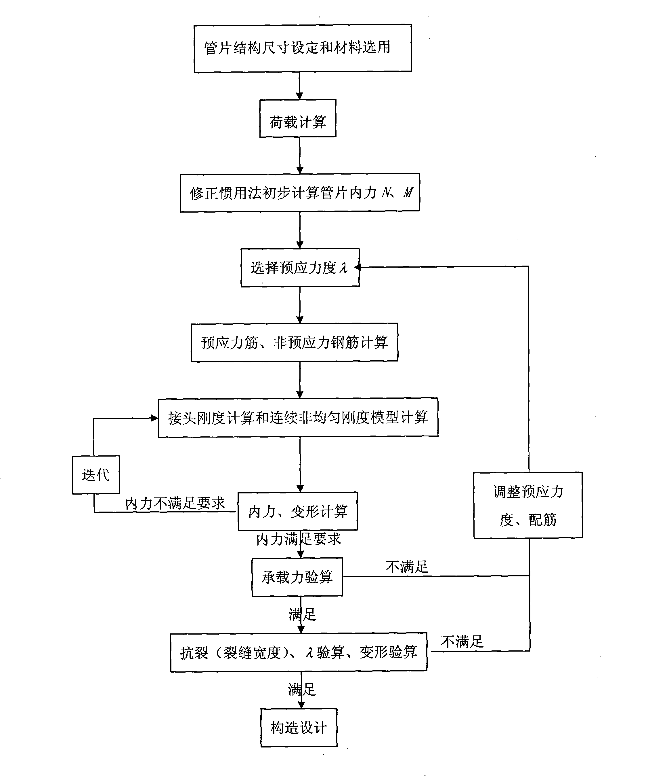
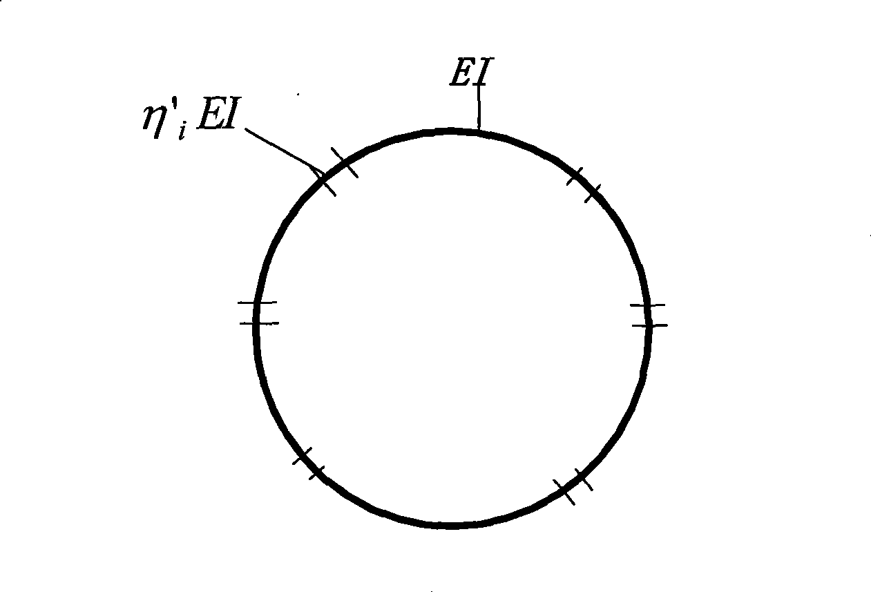
The present invention discloses a method for designing a shield tunnel prestressed liner. Firstly, the steps of setting duct piece structure and size, selecting material, calculating load and calculating the structure internal force primarily are taken. According to the requirement of a liner structure, the prestressed liner type and prestressing strength are confirmed. A stressed reinforcement and a non-prestressed reinforcement are confirmed. Joints are calculated, and continuous uneven rigidity calculation model is confirmed. Prestressing force equivalent load is calculated and is applied to the calculation model together with the load calculated primarily to get the inner force and the distortion of the structure. The equivalent rigidity of a joint area is calculated and compared with the prior result, if the difference is not large, the subsequent calculation is processed; otherwise iterative computation is required to be processed. The calculation of the carrying capacity of the structure is checked, if the requirement is not met, the prestressing strength and reinforcement assembly are required to be adjusted, and the prestressing strength is selected again and calculated. If the carrying capacity meets the requirement, the calculation of crack resistance and crack width and the calculation of deformation are checked, and the relative component design is carried out finally.

Description

technical field [0001] The invention relates to a design method for the prestressed lining of a shield tunnel. Background technique [0002] Due to the incomparable superiority of reinforced concrete, prestressed concrete technology has been widely used in building structures, bridges and other fields. Applying prestress can improve the crack resistance of concrete on the one hand, and can also be used as a means of assembly. The introduction of prestressing technology into the prefabricated lining of shield tunnels has good economic and technical performance. [0003] In prestressed lining, the effect of prestress is mainly manifested in two aspects: [0004] (1). Influence on the joint - the application of prestress can reduce the opening angle of the joint (compared with the lining spliced ​​by bolts under the same load condition); [0005] (2). Influence on the overall structure - the application of prestress is equivalent to applying equivalent confining pressure to ...

Claims


Application Information

Patent Timeline
IPC IPC(8): E21D11/08
Inventor 朱合华廖少明刘丰军闫治国
Owner TONGJI UNIV
Why Eureka
Try Eureka