
Energy storage system control method and control device

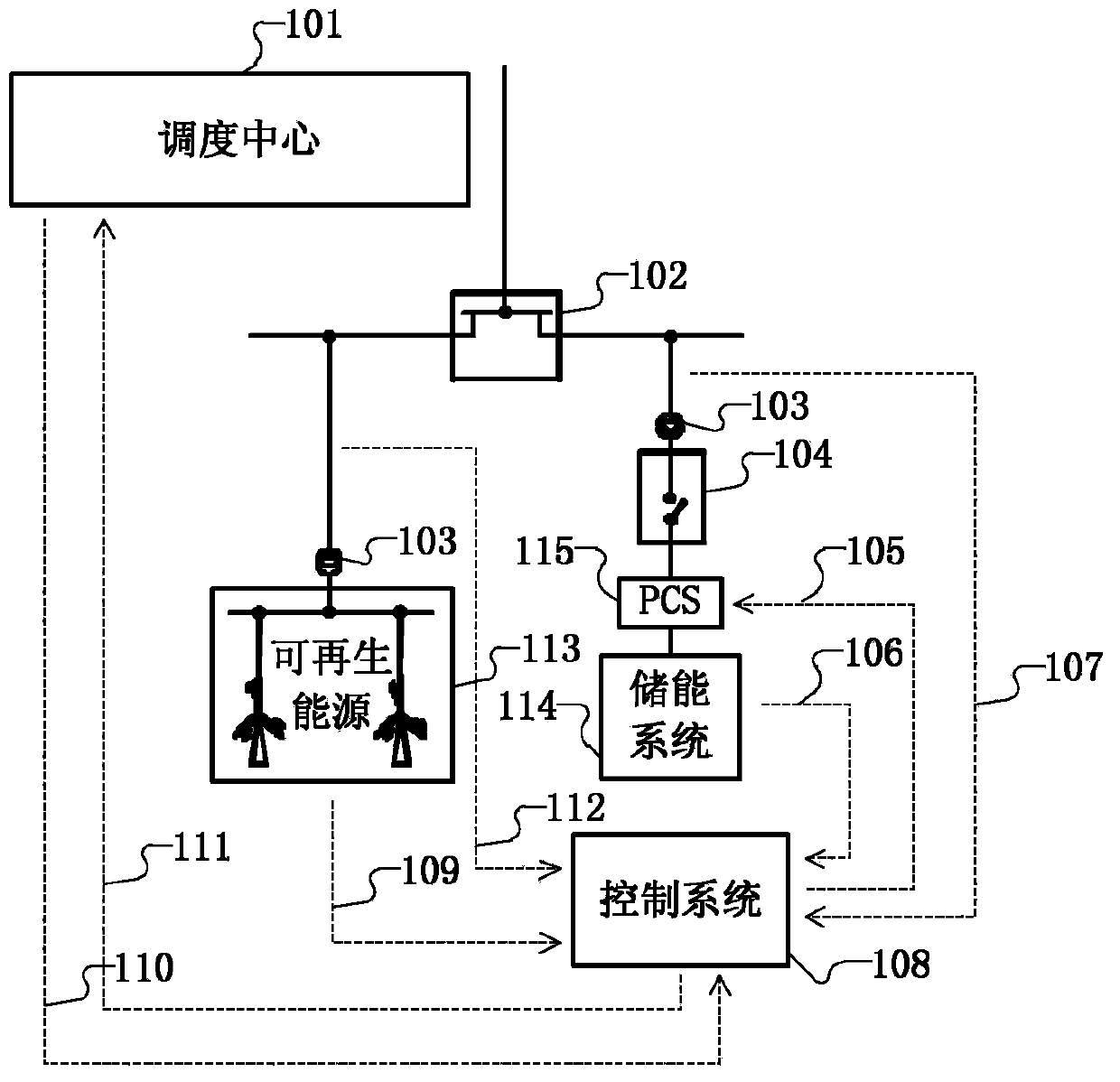
A technology of an energy storage system and a control method, applied in the field of renewable energy power generation, can solve the problems of a large amount of test data in the rule base, excessive charging and discharging actions, and the power curve is not smooth enough.

Inactive Publication Date: 2014-12-03
HITACHI LTD
View PDF5 Cites 5 Cited by
  • Summary
  • Abstract
  • Description
  • Claims
  • Application Information

AI Technical Summary

Problems solved by technology

The control algorithm of the energy storage system mentioned in this scheme, due to the delay characteristics of the algorithm, leads to an increase in the charging and discharging power of the energy storage system, which is not conducive to the long-term operation of the system
At the same time, the rule base of the algorithm requires a large amount of test data, which is difficult to implement.
[0010] The disadvantages of these methods are: the capacity limiting factor cannot be added to the real-time control of the energy storage system to protect the system hardware, the power curve is not smooth enough, and the excessive charging and discharging action

Method used


Image

  • Energy storage system control method and control device
  • Energy storage system control method and control device
  • Energy storage system control method and control device

Examples


Embodiment 1

[0049] image 3 It is a block diagram of the system structure for calculating the command value of the charging and discharging control of the energy storage system in the first embodiment. Among them, 302, 313, 314, and 315 are system noise filters, which take renewable energy power detection value 301, battery SOC detection value 316, energy storage system power detection value 317, and energy storage system temperature detection value 318 as input quantities. The filter is selected as a low-pass filter, wherein the cutoff frequency of the filter 302 can be set between the noise frequency characteristic of the renewable energy power detection system and the frequency characteristic of the actual value of the renewable energy power. The purpose is to filter out the high-frequency noise brought by the system sensor AD / DA module and the transmission line.

[0050] The parameter selection method of other filters 313 , 314 , 315 is similar to 302 .

[0051] The multi-scale anal...

Embodiment 2

[0068] Figure 5 It is a structural block diagram of the system used to calculate the command value of the charging and discharging control of the energy storage system in the second embodiment. exist Figure 5 in, with image 3 Parts with the same reference numerals in the above represent the same structures as those in Embodiment 1, and will not be repeated here.

[0069] In the second embodiment, the energy storage system receives the grid dispatching instruction or the external control command power (319), and the energy storage system controller uses the renewable energy power (included in the signal 303) and the external signal 319 to calculate the energy storage system charging Discharge target power.

[0070] 304, 320 and 321 implement an adaptive multi-scale decomposition process. Among them, the high-frequency component calculation module 320 receives the result of the multi-scale analysis, that is, the signal component 305, and obtains the highest frequency comp...


PUM


Abstract

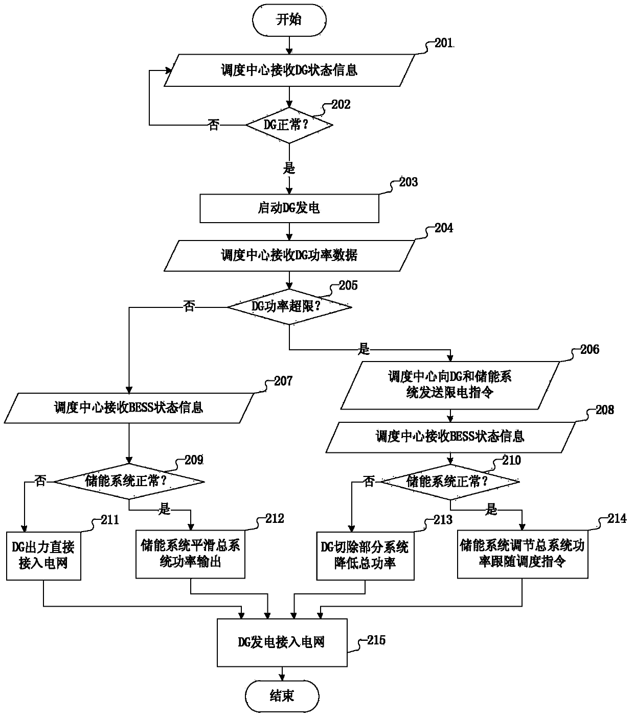
According to the invention, an energy storage system control method used for a renewable energy power generation system capable of being grid-connected to an electric power system is provided. The method comprises the following steps that a current power value of power generated by the renewable energy power generation system is acquired; whether the acquired current power value surpasses a limit power instruction value is judged; an energy storage system is started to follow the limit power instruction value under the situation that the acquired current power value surpasses the limit power instruction value and the energy storage system is normal; and the energy storage system is started to smoothen total output power of the system under the situation that the acquired current power value does not surpass the limit power instruction value and the energy storage system is normal, wherein total output power of the system is the sum of power of the renewable energy power generation system and power of the energy storage system.

Description

technical field [0001] The present invention relates to the operation of renewable energy power generation, in particular, to a control method and control device for an energy storage system of a renewable energy power generation system that can be connected to the power system. Compared with the prior art, the Under the same stable output effect, the charging and discharging power of the energy storage system can be reduced, and the capacity will not exceed the limit. Background technique [0002] With the development of human society, the capacity of power generation system is getting larger and larger. The traditional power generation methods are thermal power (coal or oil) power generation and hydropower generation. Renewable energy power generation represented by solar energy and solar energy has received more and more attention and research, and the proportion of renewable energy power generation to total power generation and grid capacity is increasing day by day. ...

Claims


Application Information

Patent Timeline
Patent Type & Authority Applications(China)
IPC IPC(8): H02J3/28
CPCY02E70/30
Inventor 单联柱董嘉挺
Owner HITACHI LTD
Learn More