Special dismantling device for liner bolts and flanges of large mills

A technology for dismantling devices and mills, applied in metal processing, metal processing equipment, manufacturing tools, etc., can solve problems such as increasing the difficulty of construction, reducing construction safety, and difficulty in getting out of the feeding port, and achieves the speed and height of realization. , Improve the effect of disassembly efficiency

Active Publication Date: 2016-09-28
重庆博视知识产权服务有限公司
View PDF5 Cites 0 Cited by
  • Summary
  • Abstract
  • Description
  • Claims
  • Application Information

AI Technical Summary

Problems solved by technology

Bolts are pierced from the inside to the outside, and there are nuts on the outer ends of the bolts. When removing the bolts, first remove the nuts, and then drive the bolts inwards. Manual work is not only labor-intensive, but also prolongs the large-scale operation to a large extent. The time for mill maintenance is reduced, and the safety of construction is also reduced
[0004] Since the feed port of the wet mill is in contact with the material for a long time, it is often difficult to remove the flange of the feed port of the mill from the feed port. It is time-consuming and laborious to remove the flange of the feed port of the mill. If it is purely manual operation , increasing the difficulty of construction

Method used


Image

  • Special dismantling device for liner bolts and flanges of large mills
  • Special dismantling device for liner bolts and flanges of large mills

Examples


Embodiment Construction

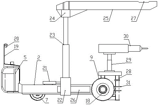
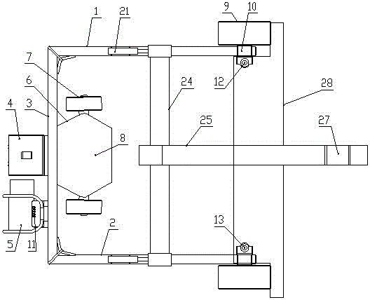
[0028] like figure 1 and figure 2 As shown, the large-scale mill liner bolt and flange special dismounting device of the present invention includes a left longitudinal beam 1 and a right longitudinal beam 2 arranged in parallel along the front and rear directions, between the rear ends of the left longitudinal beam 1 and the right longitudinal beam 2 Connected by a beam 3, the rear side of the beam 3 is provided with a hydraulic power station 4 and the driving console 5, the front side of the beam 3 is provided with a bracket 6, the left and right sides of the bracket 6 are respectively provided with a steering wheel 7, and the bracket 6 is provided with A hydraulic steering system 8 that controls the simultaneous steering of two steering wheels 7, a driving wheel 9 is respectively provided at the front ends of the left longitudinal beam 1 and the right longitudinal beam 2, and a hydraulic travel motor 10 is connected to the center of each driving wheel 9, respectively. A le...


PUM


Abstract

A dismounting device special for lining plate bolts and a flange of a large mill comprises a left longitudinal beam and a right longitudinal beam which are arranged in the front and back direction in parallel. The rear end of the left longitudinal beam and the rear end of the right longitudinal beam are connected through a transverse beam, a hydraulic power station and a driving console are arranged on the rear side of the transverse beam, a support is arranged on the front side of the transverse beam, the left side and the right side of the support are respectively provided with a steering wheel, the front end of the left longitudinal beam and the front end of the right longitudinal beam are respectively provided with a driving wheel, a left jacking hydraulic cylinder is arranged on the right side of the front end of the left longitudinal beam, and a right jacking hydraulic cylinder is arranged on the left side of the front end of the right longitudinal beam; a frame is arranged on the left jacking hydraulic cylinder and the right jacking hydraulic cylinder, pin holes are formed in the front side face of the frame, and a bolt dismounting mechanism is arranged on the frame; a hydraulic telescoping lifting system used for dismounting the flange on a feeding port of the mill is arranged on the left longitudinal beam and the right longitudinal beam. The dismounting device can freely turn, travel and perform actions such as dismounting the lining plate bolts and removing the flange on the feeding port of the mill according to the actual situation on site, labor intensity of workers is fully reduced, and dismounting efficiency is greatly improved.

Description

technical field [0001] The invention belongs to the technical field of special equipment for maintenance of large mills, and in particular relates to a special disassembly device for liner bolts and flanges of large mills. Background technique [0002] The traditional large-scale mills mainly adopt the method of manpower and driving when they are overhauled. Some enterprises cannot use the driving due to the limitation of the workshop, so they can only use pure manual methods to remove the bolts on the mill liner and remove the mill inlet. flange. [0003] Due to long-term operation, the liner plate installed on the inner wall of the mill drum will be smashed, which requires regular replacement of the liner plate. The liner is fixed to the inner wall of the mill drum by bolts, and the bolts will also corrode or deform along with the liner. When changing the liner, the bolts must be removed first. Bolts are pierced from the inside to the outside, and there are nuts on the ...

Claims


Application Information

Patent Timeline
Patent Type & Authority Patents(China)
IPC IPC(8): B23P19/04
CPCB23P19/04
Inventor 郑轶斌杜孟超王德超李光宗张淑民
Owner 重庆博视知识产权服务有限公司
Why Eureka
Try Eureka