Automatic plastic coating machine for protective tube of flexible shaft

A kind of plastic wrapping machine, automatic technology, applied in the direction of application, household utensils, tubular objects, etc., can solve the problems of increasing resistance, easy to wear the surface of the protective tube, deformation of the protective tube, etc.

Active Publication Date: 2014-12-10
佛山市盛缘行五金制品有限公司
View PDF7 Cites 1 Cited by
  • Summary
  • Abstract
  • Description
  • Claims
  • Application Information

AI Technical Summary

Problems solved by technology

[0003] Existing protective tube overmolding machine for flexible shaft is composed of inlet pipe guide, plastic extruder, water cooling device, traction mechanism and outlet guide. In the prior art, the inlet guide consists of base, support rod, The translation trough and rollers are composed. Since the height of the translation trough is corresponding to the entrance of the plastic extruder during installation, the height of the translation trough is limited. Since the coil size of the protective tube is large, the translation trough The height of the protective tube is fixed. When the protective tube enters from the input end of the translational trough, the position of the protective tube at the entrance of the translational trough changes greatly. Between the supporting frame and the roller, the protective tube is deformed, and the transition zone where the coiled protective tube transitions into a linear motion is small, and the protective tube is easy to tangle together, which affects product quality and production
[0004] The water cooling device is placed on the side of the plastic extruder to cool and quickly shape the protective tube of the plastic extruder. In order to quickly cool the shape without affecting the quality of the plastic, the input end of the water tank is connected to the plastic extruder. The distance between the machine heads is relatively short. The water cooling device in the prior art is generally an integral fixed water cooling device. However, when the machine head of the plastic extruder is repaired or replaced, it is inconvenient to operate, thus wasting time and affecting production.
[0005] In order to prevent the plastic-coated protective tube from contacting the entrance of the water-cooling tank, scratching the surface, and affecting the plastic-coating effect, it is necessary to adjust the position of the water-cooling tank so that the plastic-coated protective tube enters from the center of the entrance of the water-cooling tank as much as possible. The device is fixed as a whole, so the adjustment is inconvenient, the adjustment is laborious, and the accuracy of the adjustment position is low
[0006] When the protective pipe leaves the tank, the water in the tank will be taken out of the tank along with the protective tube and drop to the ground, thus affecting the working environment on site. What is more serious is that the water remaining on the surface of the protective tube will enter with the protective tube. to subsequent equipment, thereby affecting the normal operation of the equipment
[0007] Because the water circulation process in the tank is as follows: the water in the tank is discharged from the protective pipe inlet of the tank into the water tank, and then pumped into the tank through the water pump. When the water reaches a certain temperature, it is necessary to replenish cold water in the tank and drain it. hot water, thus wasting water
[0008] In the prior art, the plastic-coated metal sleeve is manually coiled in the barrel, and backup personnel are required to exchange it during the production process, which wastes manpower, reduces production efficiency, increases production costs, and reduces the coiling effect. Difference
[0009] In the prior art, the guide elbow is used to guide the direction of the plastic-coated protective tube, and then the protective tube is manually coiled in the barrel. Friction occurs on the inner wall of the inner wall, which increases the resistance, thereby increasing the power of the motor, which is easy to wear the surface of the protective tube and affects the appearance quality of the product

Method used


Image

  • Automatic plastic coating machine for protective tube of flexible shaft
  • Automatic plastic coating machine for protective tube of flexible shaft
  • Automatic plastic coating machine for protective tube of flexible shaft

Examples


Embodiment Construction

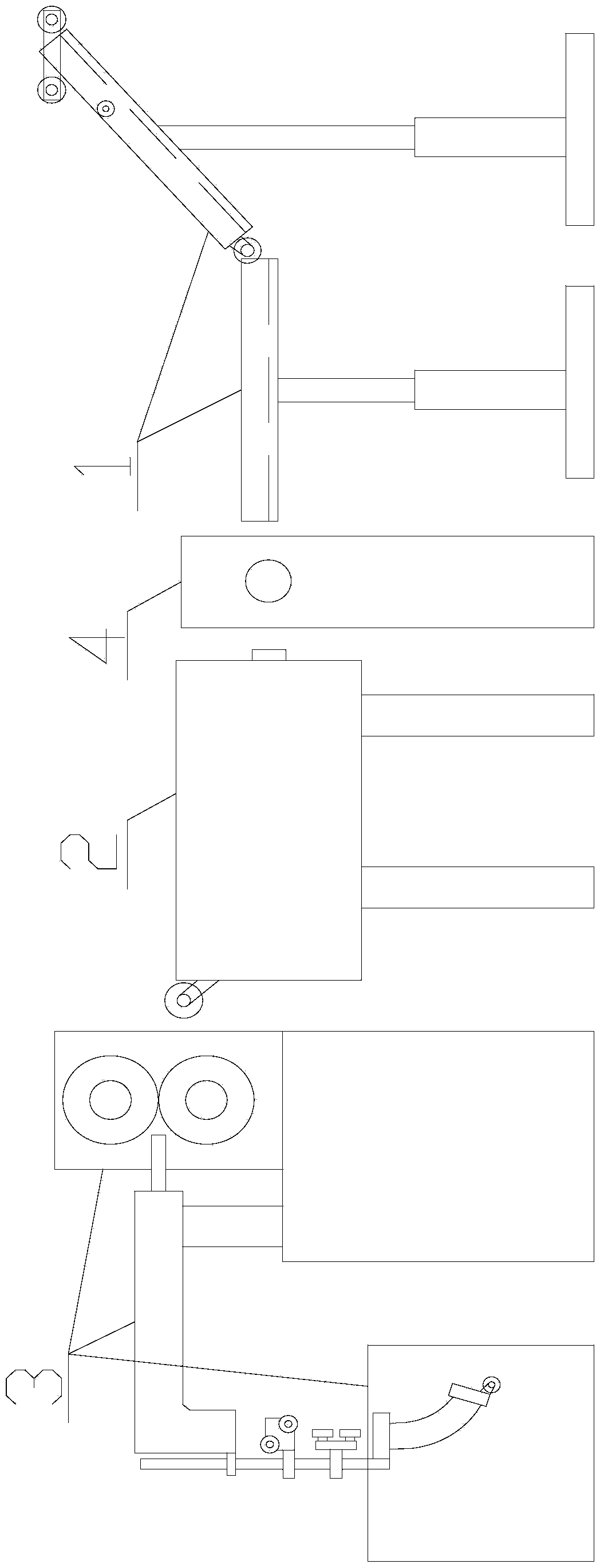
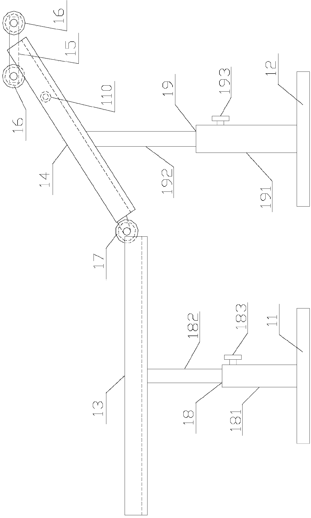
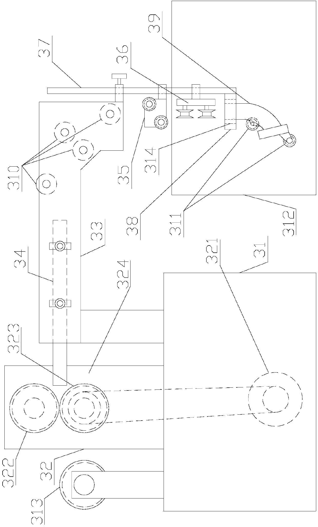
[0030] refer to figure 1 , figure 2 , image 3 , Figure 4 , Figure 5 with Image 6 , the present invention is an automatic overmolding machine for protective tubes for flexible shafts, comprising a tube inlet guide device 1, a water cooling device 2, a coiling device 3 and a plastic extruder 4, and the tube inlet guide device 1, plastic extruder 4 , the water cooling device 2 and the coiling device 3 are arranged in sequence from front to back, and the pipe inlet guide device 11 includes a first base 11, a second base 12, a first material guide trough 13, a second material guide trough 14, a third Mounting plate 15, first guide wheel 16, second guide wheel 17, first support bar 18 second support bar 19 and first positioning wheel 110, described first base 11 is provided with first support bar 18, described The first support rod 18 is provided with a first material guide groove 13, the second base 12 is provided with a second support rod 19, and the second support rod 1...


PUM


Abstract

The invention discloses an automatic plastic coating machine for a protective tube of a flexible shaft. The automatic plastic coating machine comprises an inlet tube guide device, a plastic extruder, a water cooling device and a coiling device which are sequentially arranged from the front to the rear. The automatic plastic coating machine disclosed by the invention can be conveniently adjusted, saves labor in adjustment, is high in accuracy in position adjustment, does not influence the field operating environment and normal operation of equipment and also can save manual labor and time, reduce the production cost and improve the working efficiency; a coiling effect is good, the production is not influenced, and the product quality is guaranteed.

Description

【Technical field】 [0001] The invention relates to the technical field of metal hose overmolding machines, in particular to the technical field of an automatic overmolding machine for protective tubes for flexible shafts. 【Background technique】 [0002] The flexible shaft is mainly used to connect the axes of the two transmission parts that are not on the same straight line, or the space transmission that requires relative movement between each other during work. It can bend around various obstacles and transmit rotary motion over long distances. It is suitable for occasions subject to continuous vibration to alleviate the impact, and also suitable for occasions with high speed and small torque. [0003] Existing protective tube overmolding machine for flexible shaft is composed of inlet pipe guide, plastic extruder, water cooling device, traction mechanism and outlet guide. In the prior art, the inlet guide consists of base, support rod, The translation trough and rollers ...

Claims


Application Information

Patent Timeline
Patent Type & Authority Applications(China)
IPC IPC(8): B29C47/02B29C47/08B29C47/92B29C48/92
CPCB29C48/151B29C48/28B29C48/2883B29C48/9115B29C48/92B29C2948/92933B29L2023/005
Inventor 阮仲国
Owner 佛山市盛缘行五金制品有限公司
Why Eureka
Try Eureka