Conveying mechanism with turnover function

A technology of transmission mechanism and function, applied in the direction of conveyor objects, transportation and packaging, etc., can solve the problems of unreasonable design, unsuitable for kitchen utensil manufacturing, poor practicability, etc. Effect

Inactive Publication Date: 2014-12-10
福建鑫天宏电子科技有限公司
View PDF7 Cites 22 Cited by
  • Summary
  • Abstract
  • Description
  • Claims
  • Application Information

AI Technical Summary

Problems solved by technology

[0004] The above-mentioned scheme has improved the prior art to a certain extent, but there are at least the following defects in this scheme: the design is unreasonable, it cannot be applied to the manufacture of kitchen utensils (cookware), and its practicability is poor.

Method used


Image

  • Conveying mechanism with turnover function
  • Conveying mechanism with turnover function
  • Conveying mechanism with turnover function

Examples


Embodiment Construction

[0024] The following are specific embodiments of the invention and in conjunction with the accompanying drawings, the technical solutions of the present invention are further described, but the present invention is not limited to these embodiments.

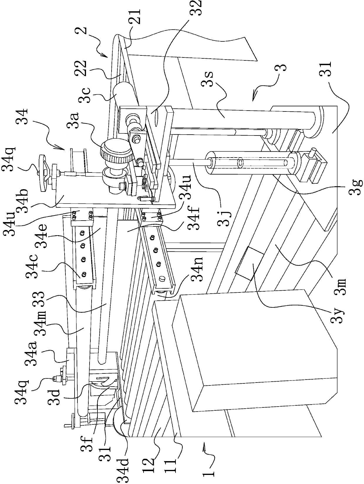
[0025] Such as Figure 1-5 As shown, the transmission mechanism with the overturning function includes a feed conveying unit 1 and a discharge conveying unit 2. The feed conveying unit 1 includes a feed conveying frame 11, and several feed rollers 12 are arranged on the feed conveying frame 11. Each feed roller 12 is respectively provided with a flexible protective cover; the discharge conveying unit 2 includes a discharge conveying frame 21, and a number of discharge rollers 22 are arranged on the discharge conveying frame 21. Roller 22 is provided with a flexible protective sheath.

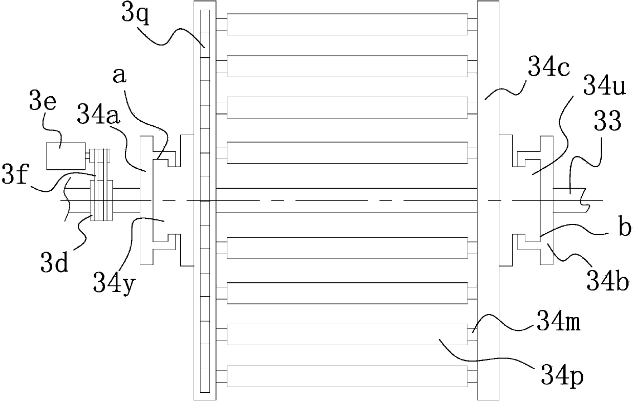
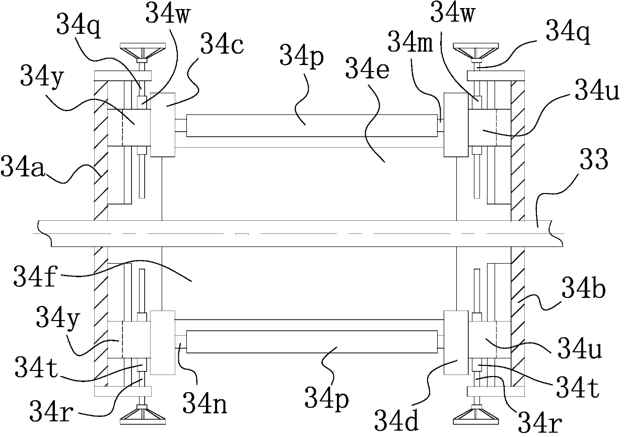
[0026] Between the feeding conveying unit 1 and the discharging conveying unit 2, an overturning conveying unit 3 is provided, and the overturning...


PUM


Abstract

The invention belongs to the technical field of mechanical manufacturing, and particularly relates to a conveying mechanism with the turnover function. The technical problems that a conveying mechanism in the prior art is poor in stability, practicality and the like are solved by the conveying mechanism. The conveying mechanism with the turnover function comprises a feeding conveying unit and a discharging conveying unit. A turnover conveying unit is arranged between the feeding conveying unit and the discharging conveying unit and comprises a rack. Two horizontally-arranged lifting frames are arranged on the rack. Each lifting frame is connected with a lifting driving mechanism capable of driving the lifting frame to ascend and descend. The lifting frames ascend and descend synchronously. A turnover shaft is arranged between the two lifting frames and connected with a rotary driving mechanism capable of driving the turnover shaft to rotate. A mechanical arm used for obtaining and releasing a workpiece is arranged on the turnover shaft. The conveying mechanism has the advantages of being good in stability and high in practicality and conveying capacity.

Description

technical field [0001] The invention belongs to the technical field of mechanical manufacturing, and in particular relates to a transmission mechanism with an overturning function. Background technique [0002] At present, when producing kitchen utensils, especially kitchen utensils such as metal pots and bowls, these kitchen utensils all have a depression, which needs to be turned over during production and processing. Low, in order to realize the transmission production of mechanical automation, more and more automatic transmission mechanisms have been developed. [0003] For example, the Chinese patent document discloses a workpiece turning transmission device [Application No.: 201320480416.9], which includes a horizontal transmission mechanism, a turning device, a ground spring, a limiter, and an inclined transmission mechanism. The horizontal transmission mechanism is hinged to one end of the turning device. , the ground spring is arranged at the bottom of the turning ...

Claims


Application Information

Patent Timeline
Patent Type & Authority Applications(China)
IPC IPC(8): B65G47/248
Inventor 赵水光
Owner 福建鑫天宏电子科技有限公司
Why Eureka
Try Eureka