

Pulley device and construction method for optical cable distribution thereby
A construction method and pulley technology, applied in the direction of components with teeth, optical fiber/cable installation, belts/chains/gears, etc., can solve the problems of extreme lateral pressure and friction of optical cables, and achieve the effect of saving resources and time
- Summary
- Abstract
- Description
- Claims
- Application Information
AI Technical Summary
Problems solved by technology
Method used
Image

Examples
Embodiment 1
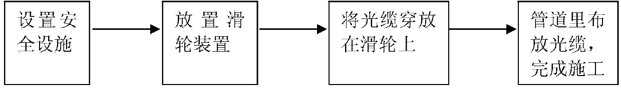
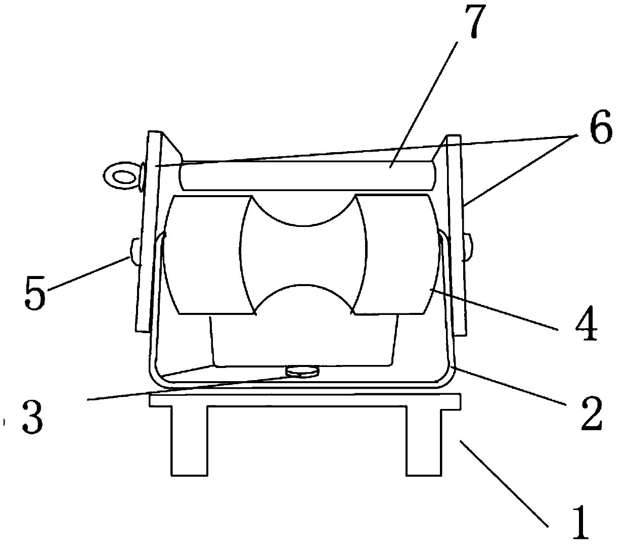
[0027] like figure 1 and figure 2 As shown, the invention provides a construction method for laying an optical cable with a pulley device, the method comprising the steps of:
[0028] Step 1: Set up safety facilities around the construction manhole;
[0029] Place safety cones, safety warning signs, etc.;
[0030] Step 2: Place a pulley device around the well, place the pulley device on the well in the direction of laying the optical cable, and buckle the base on the well ring;
[0031] Step 3: Adjust the angle of the pulley device, and put the optical cable on the pulley 4;
[0032] According to the force direction of the optical cable construction, adjust the angle of the U-shaped block 2 of the pulley device, put the optical cable on the pulley 4, and the pulley 4 rotates through the bearing of the bearing screw 5 in the middle of the U-shaped block 2;
[0033] Step 4: Lay optical cables in the construction pipeline to complete the construction.
[0034] Among them, b...
PUM
| Property | Measurement | Unit |
|---|---|---|
| Thickness | aaaaa | aaaaa |
| Length | aaaaa | aaaaa |
| Width | aaaaa | aaaaa |
Abstract
Description
Claims
Application Information