Cam lifting control system

A technology of lifting control and cam, applied in the field of cam lifting control system, can solve the problems of infeasibility, unfavorable driving mechanism, difficult setting, etc., and achieve the effect of balanced force and stable phase position.

Active Publication Date: 2014-12-10
江阴圆方机械制造有限公司
View PDF4 Cites 0 Cited by
  • Summary
  • Abstract
  • Description
  • Claims
  • Application Information

AI Technical Summary

Problems solved by technology

Frequent application of active drive force is not good for the drive mechanism
In the case of absence or failure of the driving power unit, the transfer of one phase of the cam to another becomes difficult and infeasible

Method used


Image

  • Cam lifting control system
  • Cam lifting control system
  • Cam lifting control system

Examples


Embodiment Construction

[0024] The present invention will be described in detail below through specific examples in conjunction with the accompanying drawings.

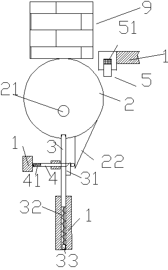
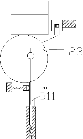
[0025] A cam lifting control system is used for lifting objects, the system includes: a cam lifting mechanism, a controller, an electromagnetic attraction device driving circuit, a motor driving circuit, and a driving shaft motor, and the cam lifting mechanism is used to control the movement of the object 9 Lifting, and including frame 1, eccentric wheel 2, locking pin 3, elastic push pin 4 and limit column 5, the shape of said eccentric wheel 2 is generally a circular shape, and is provided with a driving shaft 21 eccentrically, when When the center of the circular shape is located above the driving shaft 21 and forms a vertical relationship with it, the eccentric wheel 2 raises the object 9 to a high position; Inwardly recessed locking hole 23, the locking hole 23 is used to cooperate with the upper end of the locking pin 3, when the eccen...


PUM


Abstract

A cam lifting control system is used for lifting objects. The system comprises a cam lifting mechanism, a controller, an electromagnetic attraction device driving circuit, a motor driving circuit and a driving rotary shaft motor. The cam lifting mechanism is used for controlling an object to ascend and descend and comprises a rack (1), an eccentric wheel (2), a locking pin (3), an elastic push pin (4) and a limiting post (5). The eccentric wheel (2) is round as a whole and eccentrically provided with a driving rotary shaft (21). When the circle center of the round shape is located above the driving rotary shaft (21) and the circle center of the round shape and the driving rotary shaft (21) are in the vertical direction, the object (9) is lifted to a high position by the eccentric wheel (2). A locking hole (23) sunken inward in the radial direction is further formed in the circumferential face of the eccentric wheel (2), the locking hole (23) is used for being matched with the upper end of the locking pin (3), and when the object (9) is lifted to a high position by the eccentric wheel (2), the locking hole (23) is located below the driving rotary shaft (21) and the locking hole (23) and the driving rotary shaft (21) are in the vertical direction.

Description

[0001] technical field [0002] The present application relates to a lifting mechanism, in particular to a cam lifting control system. [0003] Background technique [0004] The cam mechanism is a high-level mechanism composed of three basic components: the cam, the follower and the frame. The cam is a component with a curved profile or a groove, generally a driving part, which performs constant-speed rotary motion or reciprocating linear motion. [0005] The component that is in contact with the cam profile, transmits power and realizes a predetermined law of motion, generally performs reciprocating linear motion or swings, and is called a follower, or an object that is lifted. [0006] The basic feature of the cam mechanism in application is that it can make the follower obtain more complex motion laws. Because the motion law of the follower depends on the cam profile curve, so in application, it is enough to design the cam profile curve according to the motion law o...

Claims


Application Information

Patent Timeline
Patent Type & Authority Applications(China)
IPC IPC(8): B66F3/44
Inventor 刘美福
Owner 江阴圆方机械制造有限公司
Why Eureka
Try Eureka