Portable binocular pupil detection device

A detection device and portable technology, applied in the field of visual inspection, can solve the problems of inconvenient operation, low frame rate of camera acquisition, limited operation efficiency, etc., to improve frame rate and tracking accuracy, ensure the accuracy of measurement results, and facilitate observation and analysis. Effect

Active Publication Date: 2015-07-01
SUZHOU INST OF BIOMEDICAL ENG & TECH CHINESE ACADEMY OF SCI
View PDF5 Cites 6 Cited by
  • Summary
  • Abstract
  • Description
  • Claims
  • Application Information

AI Technical Summary

Problems solved by technology

[0007] (1) Measurement content and accuracy are limited: hand-held pupil penlights, flashlights, etc. cannot objectively, quantitatively and accurately measure the pupil size and light reflection, including the inability to measure the light reflection latency and pupil contraction speed, etc. ;
[0008] (2) Poor portability: the pupil detector is bulky and heavy, and needs to be placed in a flat environment, so it is not suitable for use in the field;
[0009] (3) The detection object is limited: the existing equipment, the stimulation time of the stimulating light source is fixed, and the disease cannot be checked for special patients, such as patients with severe coma;
[0010] (4) Inconvenient operation and susceptible to interference from subjective factors: Traditional pupil detector equipment requires manual participation in many test procedures. The differences in manual operations and subjective judgments may lead to inaccurate tests and require the cooperation of the subjects Very high, it will bring discomfort to the subject;
[0011] (5) Poor real-time performance: The camera acquisition frame rate of the existing pupil detection equipment is low, and the real-time performance of the pupil measurement software is poor, so the measurement accuracy is limited;
[0012] (6) Limited operating efficiency: Existing portable devices do not support binocular pupillary light reflex inspection, and cannot screen patients with abnormal indirect light reflex;
[0013] (7) The measurement result is not intuitive: the existing pupil light reflex equipment provides the measurement result parameters, and there is no intuitive change curve

Method used


Image

  • Portable binocular pupil detection device
  • Portable binocular pupil detection device
  • Portable binocular pupil detection device

Examples


Embodiment 1

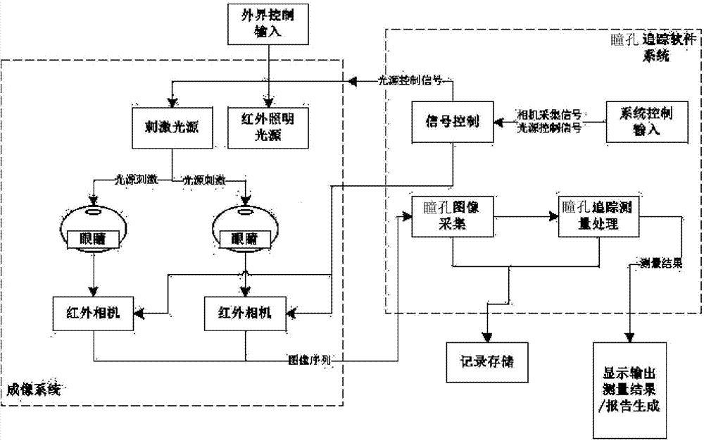
[0039] This embodiment illustrates the system architecture of the present invention.

[0040] combined with figure 1, which is a schematic diagram of the system structure of the present invention, and the system includes a graspable binocular pupil detection device imaging system and a pupil tracking measurement module. Among them, the imaging system includes two infrared cameras, two infrared lighting sources, two stimulating light sources, a grasping device and a single-chip microcomputer. The infrared camera, lighting source, stimulating light source and single-chip microcomputer are integrated inside the grasping device. Single-chip microcomputer connection, the single-chip microcomputer is responsible for signal control and data input and output; the pupil tracking measurement module is integrated in the single-chip microcomputer, and the image collected by the single-chip microcomputer is tracked and measured, and the measurement results are analyzed and processed, and f...

Embodiment 2

[0046] This embodiment is carried out on the basis of the foregoing embodiment 1. The difference from the foregoing embodiment 1 is that this embodiment describes the appearance and structure of the system of the present invention in detail.

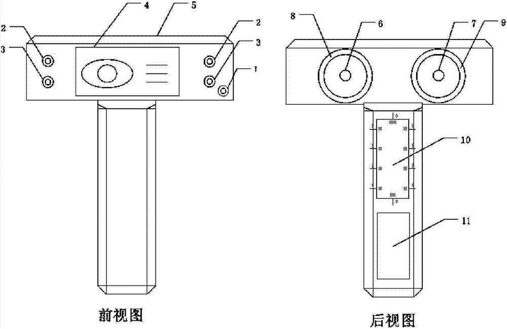
[0047] In conjunction with accompanying drawing 2, it is a schematic diagram of an appearance structure of the present invention, including a front view and a rear view ( Figure 2a ) and top view ( Figure 2b ).

[0048] The present invention is a grasping measuring device, which includes infrared cameras 12 and 13, and the two cameras are independently and directly controlled by a single-chip microcomputer to respectively complete image acquisition and finally connect with the pupil tracking measurement module; combined with the attached Figure 2a , the top of the gripping device is the measuring part, and the lower part is the handle.

[0049] Infrared lighting sources 14 and 15 are installed in the device, which are controlled by ...

Embodiment 3

[0056] This embodiment is carried out on the basis of the foregoing embodiment 1 or 2. The difference from the foregoing embodiments is that the pupil tracking measurement module is designed in this embodiment.

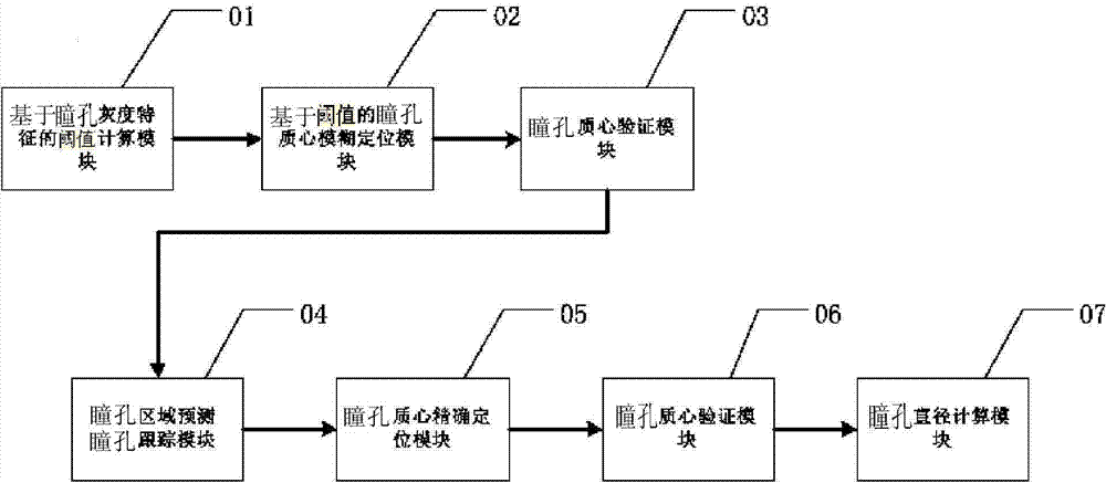
[0057] combined with image 3 , which is a schematic diagram of the pupil tracking measurement module of the present invention. After the system module inputs the pupil image, the pupil threshold is calculated by the threshold calculation module 01 based on the gray feature of the pupil. Based on the pupil threshold, the pupil centroid fuzzy positioning module 02 blurs the pupil centroid Positioning calculation, get the rough center of mass of the pupil, and verify the validity of the pupil centroid through the pupil centroid verification module 03, if it is invalid, the tracking will fail, otherwise, the pupil area is predicted by the pupil area prediction pupil tracking module 04, and the pupil is precisely positioned within the predicted area , that is, the precise...


PUM


Abstract

The invention discloses a portable binocular pupil detection device. The portable binocular pupil detection device comprises a grabbing type binocular pupil detection equipment imaging system and a pupil tracking and measuring module. The imaging system comprises two infrared cameras, two infrared illumination light sources, two stimulation light sources, grabbing equipment and a single-chip microcomputer, wherein the infrared cameras, the illumination light sources, the stimulation light sources and the single-chip microcomputer are integrated in the grabbing equipment, the cameras are connected with the light sources and the single-chip microcomputer, and the single-chip microcomputer takes charge of control of signals and input and output of data; the pupil tracking and measuring module is integrated on the single-chip microcomputer, images collected by the single-chip microcomputer are tracked and measured, and the measurement result is analyzed and processed. The portable binocular pupil detection device is high in portability and can be applied to the occasions of emergency rescue, fields and the like, the measurement result is accurate and visual, and the portable binocular pupil detection device has broad application prospects.

Description

technical field [0001] The invention belongs to the field of visual detection, and in particular relates to a portable binocular pupil detection device, which includes an infrared camera, an infrared illumination light source, a stimulation light source, a grasping device, a measurement display device, a single-chip microcomputer control, a data processing control module and pupil tracking measurement System modules are suitable for medical applications in clinical ophthalmology, neurosurgery, psychiatry and related fields. Background technique [0002] When the human eye is stimulated by light, the pupil narrows, which is called the pupillary light reflex. The constriction of the pupil is accomplished by the pupillary sphincter muscle innervated by the parasympathetic nerve in the oculomotor nerve, and the dilation of the pupil is accomplished by the pupillary dilator muscle innervated by the sympathetic nerve. The reflex on the same side is called the direct light reflex,...

Claims


Application Information

Patent Timeline
Patent Type & Authority Applications(China)
IPC IPC(8): A61B3/11A61B3/14
Inventor 付威威周哲刘敏陈奭
Owner SUZHOU INST OF BIOMEDICAL ENG & TECH CHINESE ACADEMY OF SCI
Why Eureka
Try Eureka