Method for determining a filling quantity

A filling volume, purpose technology, applied in non-mechanical driven clutches, clutches, fluid driven clutches, etc., can solve problems such as injuries

Inactive Publication Date: 2014-12-10
DEERE & CO
View PDF0 Cites 1 Cited by
  • Summary
  • Abstract
  • Description
  • Claims
  • Application Information

AI Technical Summary

Problems solved by technology

Disadvantageous and should be avoided in any case, this power flow may lead to a clear movement of the vehicle during the calibration process, which may cause corresponding injuries in the vicinity of the tractor

Method used


Image

  • Method for determining a filling quantity
  • Method for determining a filling quantity
  • Method for determining a filling quantity

Examples


Embodiment Construction

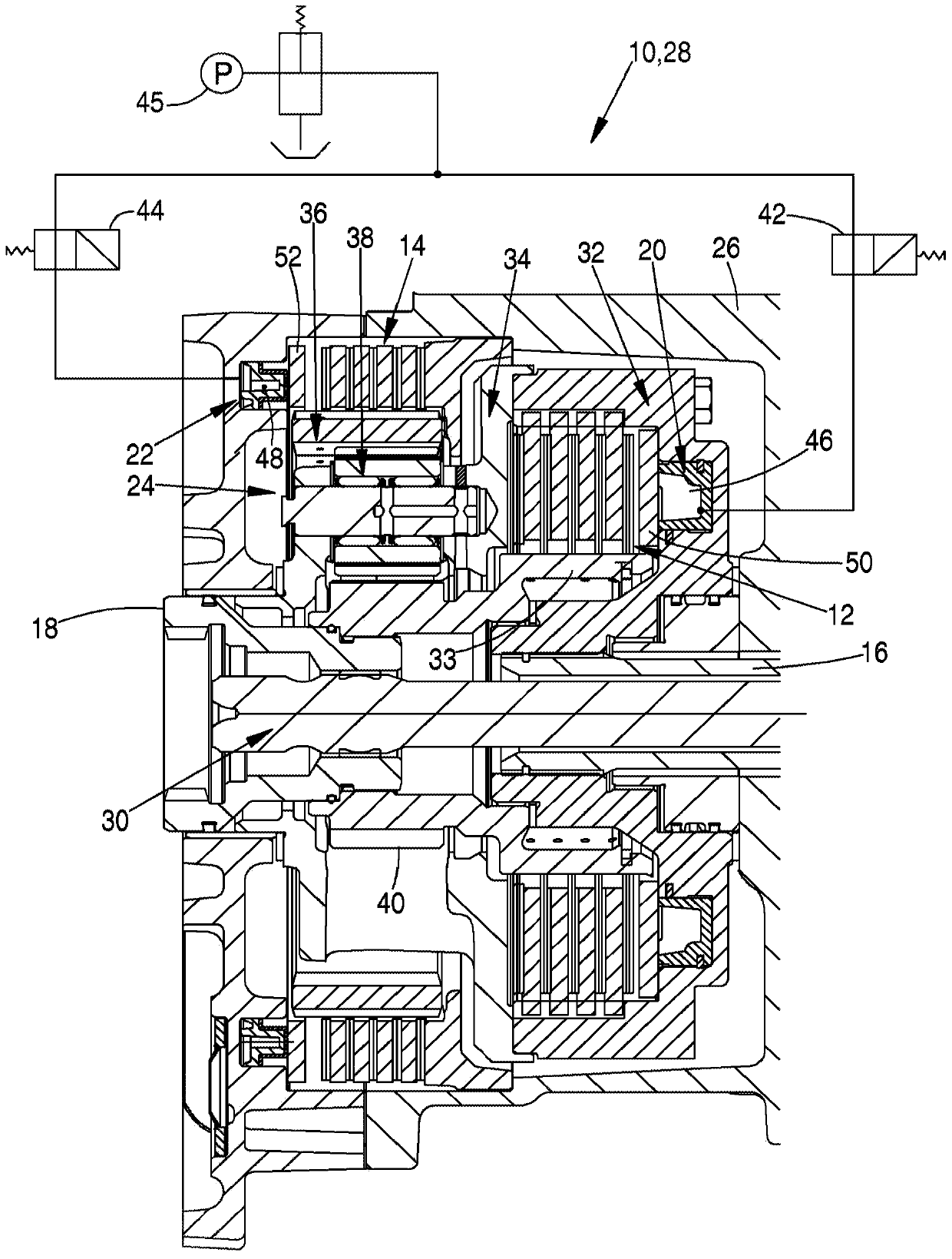
[0019] figure 1 A clutch device 10 of an agricultural utility vehicle is shown, which is designed as a reversing unit 28 and is arranged in a housing 26 . Both the input shaft 16 and the output shaft 18 are designed as hollow shafts. A shaft 30 , not described in further detail, runs inside the input shaft 16 and the output shaft 18 for example for driving a power take-off shaft of a utility vehicle.

[0020] The input shaft 16 is connectable in driving engagement with the output shaft 18 via a forward clutch 12 such that both shafts 16 , 18 have the same direction of rotation. The forward clutch 12 is here designed as a multiplate clutch. The outer plate support 32 is connected to a planetary support 34 of a transmission stage 24 designed as a double planetary gearing. The hollow gear 36 of the double planetary gear can be locked relative to the housing 26 via the reverse clutch 14 (also called reverse brake). The reverse clutch is also designed as a multi-plate clutch. ...


PUM


Abstract

The invention relates to a method for determining the filling quantity in the actuating system of a clutch arrangement (10) which has a forward clutch (12) and a reverse clutch (14) for a respective connection of an input shaft (16) to an output shaft (18) for drive purposes. A first controllable actuating unit (20) is provided for actuating the forward clutch (12), and a second controllable actuating unit (22) is provided for actuating the reverse clutch (14).

Description

technical field [0001] The invention relates to a method for determining the fill level in an actuation system of a clutch device having a forward clutch for driving purposes for a corresponding connection of an input shaft with an output shaft and a reverse clutch, wherein a first controllable actuation unit is provided for actuating the forward clutch and a second controllable actuation unit is provided for actuating the reverse clutch. Background technique [0002] In tractors of the John Deere brand, a gearbox is used, the forward and reverse clutches of the steering unit of which are released during the operation of each other, so that the actuating unit associated with the clutch is not only in the absence of The pressure is switched and the hydraulic oil in the actuating unit is at least partially evacuated. In this case, air is located in the actuating unit such that it must be removed before the corresponding clutch is switched again in the actuating unit by use of...

Claims


Application Information

Patent Timeline
Patent Type & Authority Applications(China)
IPC IPC(8): F16D48/06
CPCF16D48/066F16D2500/70406F16D2500/30415F16D2500/111F16D2500/1026F16D2500/30428F16D2500/1045F16D2500/10412F16D2500/5014F16D2500/30426F16D25/14
Inventor 芬克·曼纽埃尔
Owner DEERE & CO
Why Eureka
Try Eureka