

Slurry returning method
A container and an old technology, applied in the field of ceramic manufacturing, can solve the problems of unstable performance, uncontrollable mixing ratio of returned slurry, insufficient homogenization time of old slurry, etc., to achieve the effect of eliminating slurry leakage and reducing all emptying
- Summary
- Abstract
- Description
- Claims
- Application Information
AI Technical Summary
Problems solved by technology
Method used
Image

Examples
Embodiment 1
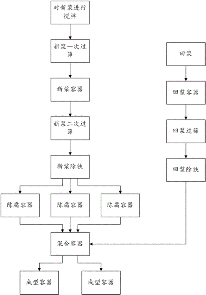
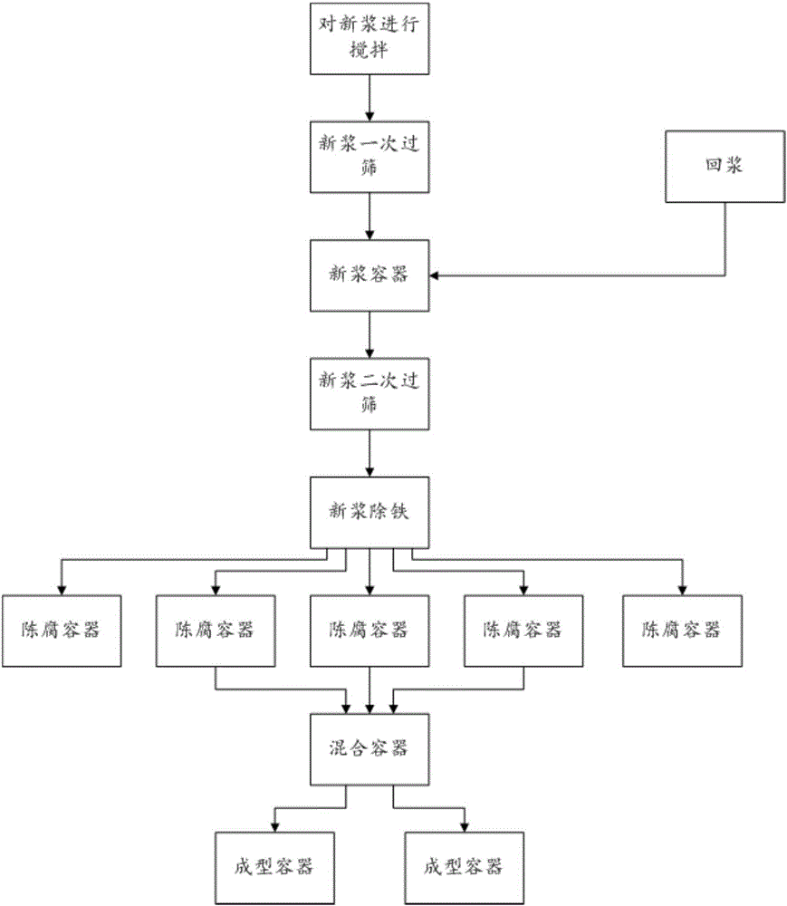
[0036] A method of resizing, comprising:
[0037] 1. Stir the new pulp.
[0038] 2. After passing through the vibrating screen with mesh 20, the new pulp after stirring is sieved once, and then poured into the new pulp container.
[0039] 3. The new pulp in the fresh pulp container is screened for the second time through a vibrating screen with a mesh size of 120.
[0040] 4. After the new pulp has been sieved for the second time by the electromagnetic separator, the new pulp is deironed, and then poured into three old containers.
[0041] 5. The new pulp is stale for 5 days in three stale containers.
[0042] 6. Pour the return slurry into the return slurry container.
[0043] 7. Pass through a vibrating screen with a mesh size of 120 to sieve the returned pulp in the returned pulp container.
[0044] 8. Use the electromagnetic separator to return the slurry after the slurry has been sieved and remove the iron, and mix it with the stale new slurry in the mixing container....
Embodiment 2
[0047] A method of resizing, comprising:
[0048] 1. Stir the new pulp.
[0049] 2. After passing through the vibrating screen with mesh 20, the new pulp after stirring is sieved once, and then poured into the new pulp container.
[0050] 3. The new pulp in the fresh pulp container is screened twice through a vibrating screen with a mesh size of 140.
[0051] 4. After the new pulp has been sieved for the second time by the electromagnetic separator, the new pulp is deironed, and then poured into three old containers.
[0052] 5. The new pulp is stale in three old containers for 8 days.
[0053] 6. Pour the return slurry into the return slurry container.
[0054] 7. Pass through a vibrating screen with a mesh size of 140 to sieve the returned pulp in the returned pulp container.
[0055] 8. Use an electromagnetic separator to return the slurry after the return slurry has been sieved to remove iron, and stir and mix with the stale new slurry in the mixing container. The stir...
Embodiment 3
[0058] A method of resizing, comprising:
[0059] 1. Stir the new pulp.
[0060] 2. After passing through the vibrating screen with mesh 20, the new pulp after stirring is sieved once, and then poured into the new pulp container.
[0061] 3. The new pulp in the fresh pulp container is screened twice through a vibrating screen with a mesh size of 130.
[0062] 4. After the new pulp has been sieved for the second time by the electromagnetic separator, the new pulp is deironed, and then poured into three old containers.
[0063] 5. The new pulp is stale in three old containers for 6 days.
[0064] 6. Pour the return slurry into the return slurry container.
[0065] 7. Pass through a vibrating screen with a mesh size of 130 to sieve the returned pulp in the returned pulp container.
[0066] 8. Use the electromagnetic separator to return the slurry after the return slurry has been sieved and remove the iron, and then stir and mix with the stale new slurry in the mixing containe...
PUM
 Abstract
Description
Claims
Application Information