Oil tank for hand tool machine and hand tool machine with oil tank

A hand-held power tool and oil tank technology, which is applied to the oil tank field of chain saws, can solve the problems of increasing the number of parts and the susceptibility to failure, and achieve the effects of reducing the number of parts, reducing costs, and avoiding blockage

Active Publication Date: 2022-03-01
ROBERT BOSCH GMBH
View PDF10 Cites 0 Cited by
  • Summary
  • Abstract
  • Description
  • Claims
  • Application Information

AI Technical Summary

Problems solved by technology

This increases the number of parts and the associated susceptibility to failure

Method used


Image

  • Oil tank for hand tool machine and hand tool machine with oil tank
  • Oil tank for hand tool machine and hand tool machine with oil tank
  • Oil tank for hand tool machine and hand tool machine with oil tank

Examples


Embodiment Construction

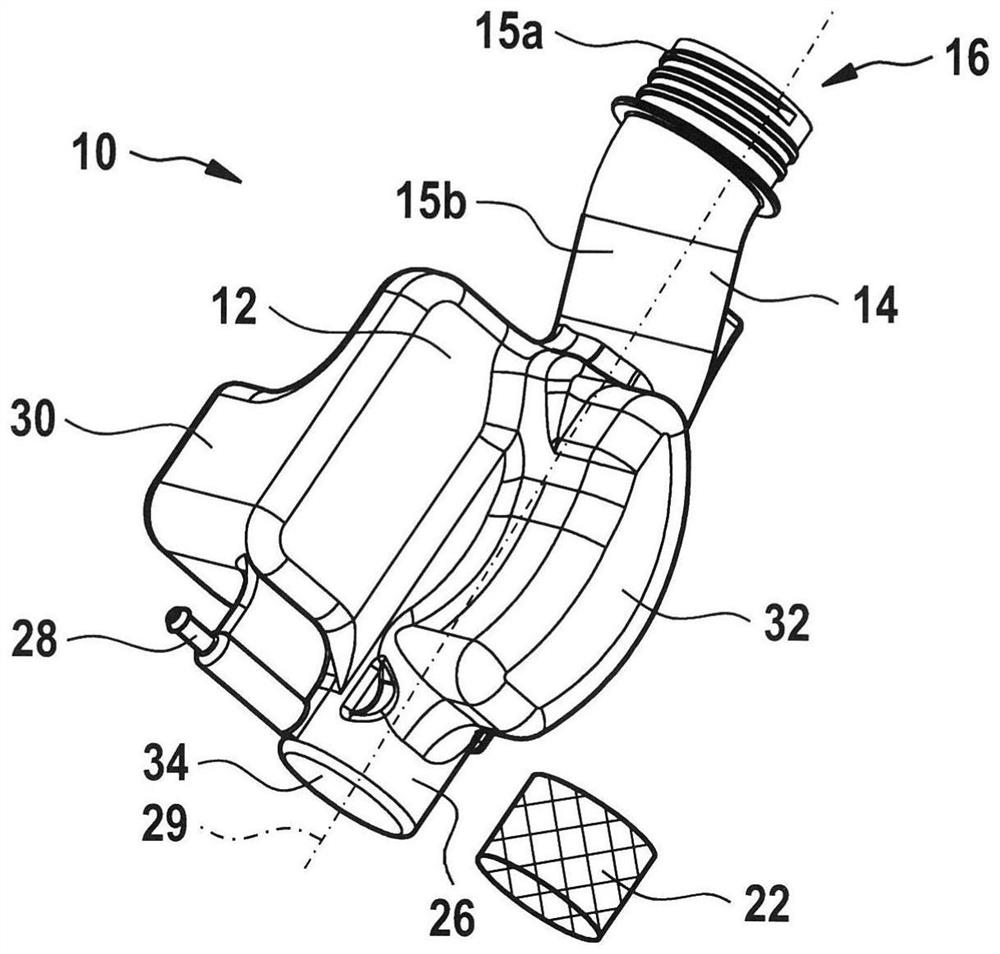
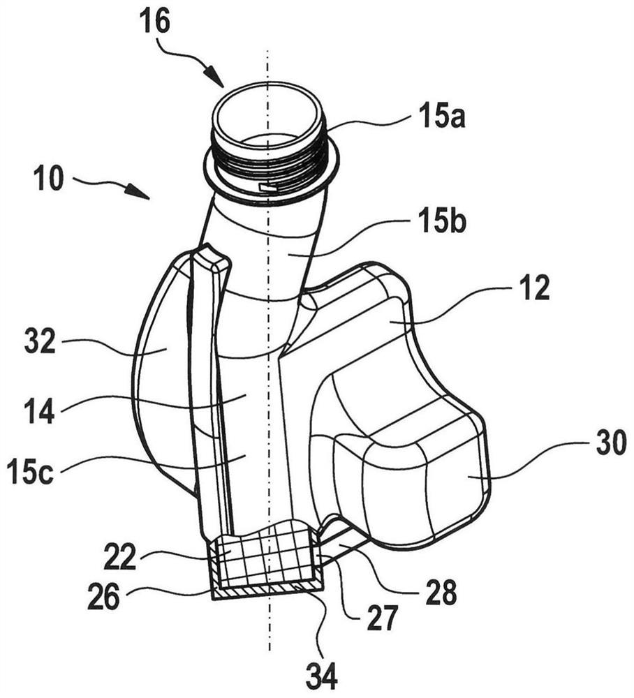
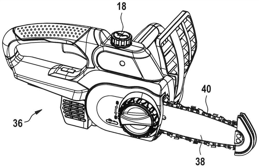
[0028] figure 1 and 2 The tank 10 is shown in each case in a perspective view. The tank 10 has a tank housing 12 and a filling connection 14 with a filling opening 16 . The filling opening 16 can be closed with a cap 18 (see image 3 ) closed. Alternatively, other closure means are also conceivable. In this case, the filling socket 14 can be configured cylindrically, but it can also have another shape or geometry, such as polygonal, funnel-shaped or the like.

[0029] filter 22 in figure 1 shown separately next to the tank housing 12 and in figure 2Shown in the sectioned area in , the filter can be introduced into the oil tank via the filling connection 14 . The filter 22 is provided for arrangement on the bottom 34 of the tank housing 12 . It can be fixed in the filter receptacle 26 . The filter 22 is formed from a porous, permeable material, especially elastic foam or sponge. Furthermore, the filter 22 is configured cylindrically. In principle, however, the filte...


PUM


Abstract

The invention relates to an oil tank (10) for a hand-held power tool, in particular for a chain saw (36), having at least one oil tank housing (12) with a filling opening (16) ) and an oil outlet opening (27) constructed separately from the filling opening (16). The invention proposes to provide means for fastening the filter ( 22 ) on and in the tank housing ( 12 ) in such a way that the filter covers the oil outlet opening ( 27 ).

Description

Background technique [0001] Hand-held power tools such as chainsaws require lubricants, in particular oils, at least for the lubrication of the chain revolving on the teeth or its links. For this purpose, chain saws typically have a refillable oil or lubricating oil tank as well as an oil delivery system with pumps, hoses, etc. [0002] In order to avoid blockage or clogging of the oil delivery system, especially the oil outlet opening of the oil tank, oil delivery pump, hose, valve, nozzle, etc., a filter is provided. Typically, the filter is formed from screen material, grate material or foam material. Such filters are usually placed in the filling nozzle or neck of the oil tank, whereby contamination, in particular by sawdust, dust or particles, is kept away from the oil tank. When filling or refilling an oil tank, oil can slowly flow through the oil-loaded filter pores by gravity. The problem, however, is that the air in the tank must escape through the same oil-loaded ...

Claims


Application Information

Patent Timeline
Patent Type & Authority Patents(China)
IPC IPC(8): B23D57/02B23D59/00
CPCB23D57/023B23D59/00B27B17/00B27B17/12
Inventor A·法尔卡斯C·斯穆特克C·费埃尔G·博尔希克P·海伍德R·普尔D·毛约罗什
Owner ROBERT BOSCH GMBH
Why Eureka
Try Eureka