Power conversion device

一种功率转换装置、开关元件的技术,应用在输出功率的转换装置、交流功率输入变换为交流功率输出、电气元件等方向,能够解决双向开关损坏等问题,达到抑制浪涌电压的效果

Active Publication Date: 2014-12-10
FUJI ELECTRIC CO LTD
View PDF1 Cites 6 Cited by
  • Summary
  • Abstract
  • Description
  • Claims
  • Application Information

AI Technical Summary

Problems solved by technology

Then, the bidirectional switches 2 and 3 may be damaged by the surge voltage generated in the reactor L or the reactor 5

Method used


Image

  • Power conversion device
  • Power conversion device
  • Power conversion device

Examples


Embodiment Construction

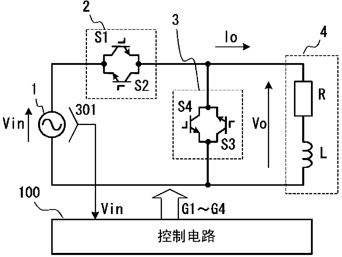
[0051] Below, refer to Figure 1 to Figure 10 Embodiments of the power conversion device to which the present invention is applied will be described in detail.

[0052] figure 1 It is a figure for demonstrating Embodiment 1 of the power conversion apparatus to which this invention is applied.

[0053] In the figure, 1 is a single-phase AC power supply, 2 and 3 are bidirectional switches, 4 is a load, and 100 is a control circuit. The power conversion device according to this embodiment is a step-down AC chopper that supplies a voltage Vo obtained by stepping down a voltage Vin of a single-phase AC power supply 1 to a load.

[0054] The bidirectional switch 2 (first bidirectional switch) is a circuit in which switching element S1 (first switching element) and switching element S2 (second switching element) are connected in antiparallel. Let the collector terminal side of the switching element S1 be the first terminal of the bidirectional switch 2 , and let the emitter termi...


PUM


Abstract

A power conversion apparatus includes first, second, third, and fourth switching elements. In a first period, the second and third switching elements are switched ON, and first and fourth switching elements are alternately switched ON / OFF. In a second period, the first and fourth switching elements are switched ON, and the second and third switching elements are alternately switched ON / OFF. In a third period, the first and second switching elements are switched ON, and the third and fourth switching elements are switched OFF. The power conversion apparatus provides a release path for inductive energy accumulated in a reactor.

Description

technical field [0001] The invention relates to a power conversion device for stepping down or boosting the voltage of an AC power supply and outputting the AC voltage. Background technique [0002] A buck-type or boost-type AC chopper is known as a power conversion device that steps down or boosts the voltage of an AC power supply to output an AC voltage. Figure 11 This is a diagram for explaining the single-phase step-down AC chopper disclosed in Patent Document 1. FIG. [0003] In the figure, 1 is a single-phase AC power supply, 2 and 3 are bidirectional switches, and 4 is a load. [0004] The bidirectional switch 2 is a circuit in which switching elements S1 and S2 are connected in reverse series, wherein the switching elements S1 and S2 are respectively connected in antiparallel to diodes. The bidirectional switch 3 is a circuit in which switching elements S3 and S4 are connected in anti-series, wherein the switching elements S3 and S4 are respectively connected in an...

Claims


Application Information

Patent Timeline
Patent Type & Authority Applications(China)
IPC IPC(8): H02M5/257
CPCH02M2005/2932H02M5/293H02M5/2573H02M5/2932
Inventor 坂野正太郎藤田悟
Owner FUJI ELECTRIC CO LTD
Why Eureka
Try Eureka