Control apparatus for switching device

一种开关器件、控制装置的技术,应用在电子开关、电气程序控制、顺序/逻辑控制器中的程序控制等方向,能够解决浪涌电压抑制不可能等问题,达到抑制浪涌电压的效果

Active Publication Date: 2013-04-24
FUJI ELECTRIC CO LTD
View PDF8 Cites 6 Cited by
  • Summary
  • Abstract
  • Description
  • Claims
  • Application Information

AI Technical Summary

Problems solved by technology

[0008] However, a problem with this prior art arrangement is that when the switching device is not in an overcurrent state, but suppression of the surge voltage when the switching device current is cut off is necessary for the purpose of overcurrent protection, such surge voltage suppression is not possible

Method used


Image

  • Control apparatus for switching device
  • Control apparatus for switching device
  • Control apparatus for switching device

Examples


Embodiment Construction

[0024] Hereinafter, various embodiments of the present invention are explained based on the drawings.

[0025] (Outline of the first embodiment)

[0026] The first embodiment of the control apparatus for switching devices of the present invention is applied to intelligent power modules (IPM) used in inverters for driving motors and similar applications.

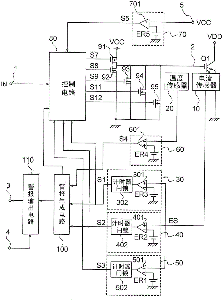
[0027] Such as figure 1 As shown, the control device includes an input terminal 1, an output terminal 2, an alarm output terminal 3, a reset terminal 4, and a power supply voltage terminal 5, and controls the switching device Q1 connected to the output terminal 2 to be turned on and off. The control device operates according to the supply voltage VCC supplied to the supply voltage terminal 5 .

[0028] The switching device Q1 includes an IGBT or the like having a rated current of, for example, several tens to several hundreds of amperes (A). When the control device is applied to an inverter, the switching device Q1 is a pa...


PUM


Abstract

An object of the present invention is to suppress surge voltages at the time of current shutoff of a switching device for the purpose of protection from overcurrents although the switching device is not in an overcurrent state. The control apparatus for a switching device of the present invention comprises a current sensor (10), a comparator (501), a timer latch (502), a control circuit (80), and a transistor (95). The current sensor (10) detects the current of a switching device (Q1) and accordingly outputs a detected voltage ES. The comparator (501) outputs a signal when the detected voltage ES is equal to or greater than a reference voltage ER1. When the time duration of the output signal is equal to or greater than a setting time, the timer latch (502) outputs a surge suppression detection signal S3. Based on this surge suppression detection signal S3, the control circuit (80) outputs, to the transistor (95), a driving signal S12 to turn off the switching device (Q1). The reference voltage ER1 is smaller than a reference voltage ER2 used when detecting an overcurrent flowing in the switching device (Q1).

Description

technical field [0001] The present invention relates to a control device for a voltage-controlled switching device such as an insulated gate bipolar transistor (IGBT), wherein the control device controls the switching device to be turned on and off. Background technique [0002] As a control device, for example, a device disclosed in Japanese Patent Application Laid-Open No. 2008-141841 is known. [0003] This prior art device includes a drive circuit that turns on and off a switching device, and a current sensor that detects a current flowing in the switching device. [0004] In addition, the prior art device includes a first comparison circuit that compares the current detected by the current sensor with a first reference value, and outputs an indication indicating that the current in the switching device is greater than or equal to the first reference value when the detected current is greater than or equal to the first reference value. The overcurrent detection signal o...

Claims


Application Information

Patent Timeline
Patent Type & Authority Applications(China)
IPC IPC(8): G05B19/04
CPCH03K17/567H03K17/082
Inventor 清水直树
Owner FUJI ELECTRIC CO LTD
Why Eureka
Try Eureka