Electric wire holding member and wire harness

a technology of holding member and wire harness, which is applied in the direction of insulated conductors, cables, conductors, etc., can solve the problems of excessive surge voltage applied to the motor, and achieve the effect of suppressing the surge voltag

Active Publication Date: 2016-12-15
YAZAKI CORP +1
View PDF16 Cites 7 Cited by
  • Summary
  • Abstract
  • Description
  • Claims
  • Application Information

AI Technical Summary

Benefits of technology

[0007]The present invention has been made in view of the above circumstances, and an object thereof is to provide an electric wire holding member and a wire harness that can suitably suppress the surge voltage.
[0015]According to still another aspect of the present invention, in the wire harness, it is possible to configure that the electric wire holding member is formed so as to enclose an overall area of the electric wire portion in the longitudinal direction of the electric wire portion.

Problems solved by technology

Such a steep rising voltage is repeatedly reflected many times between the inverter and the motor by impedance mismatching.
As a result, there is a case that an excessive surge voltage may be applied to the motor.

Method used


Image

  • Electric wire holding member and wire harness
  • Electric wire holding member and wire harness
  • Electric wire holding member and wire harness

Examples


Embodiment Construction

[0023]An embodiment of an electric wire holding member and a wire harness according to the present invention will be described below with reference to the accompanying drawings. In the following drawings, the same or corresponding elements are denoted as the same reference numerals, and the description thereof will not be repeated.

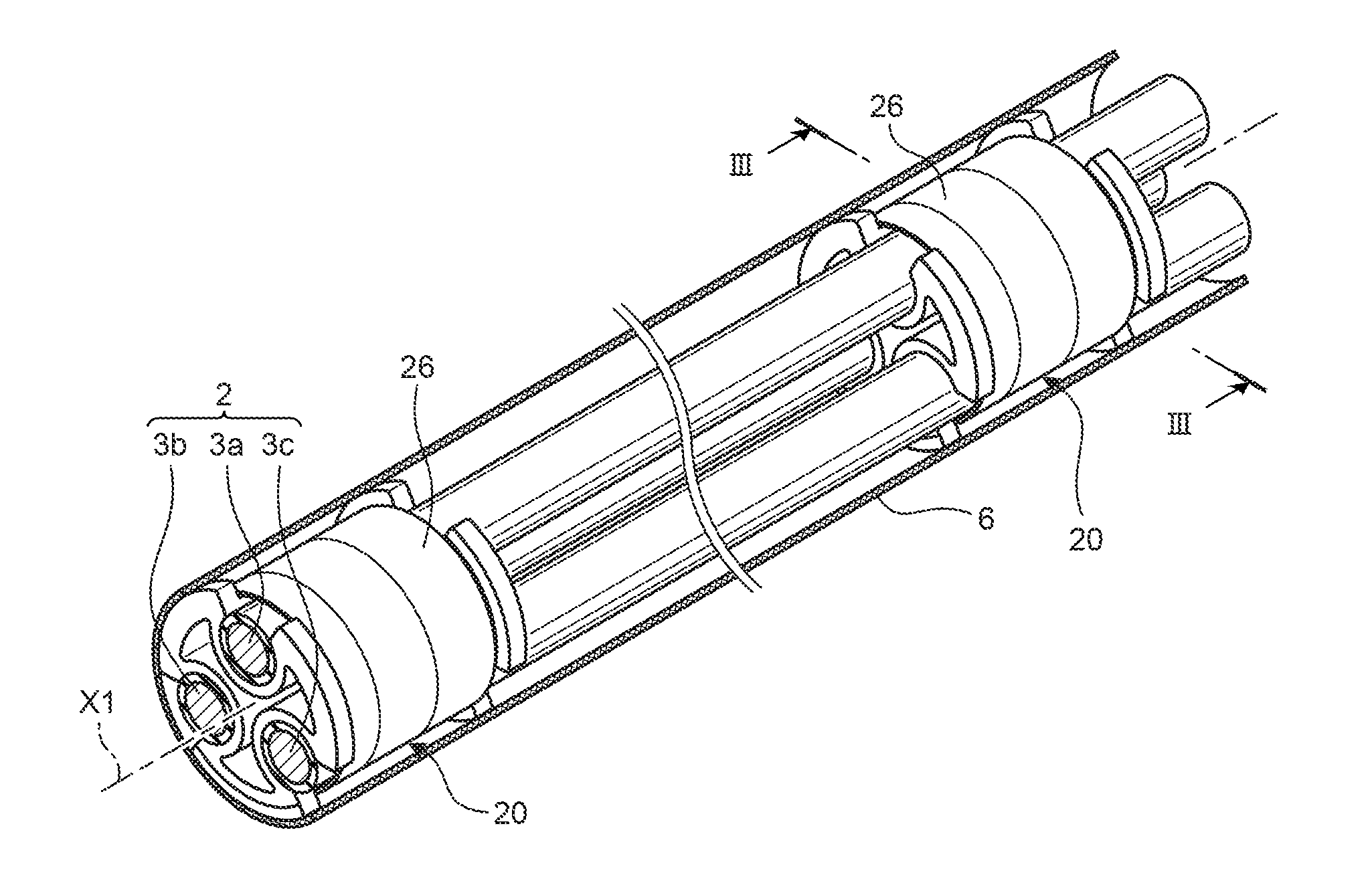
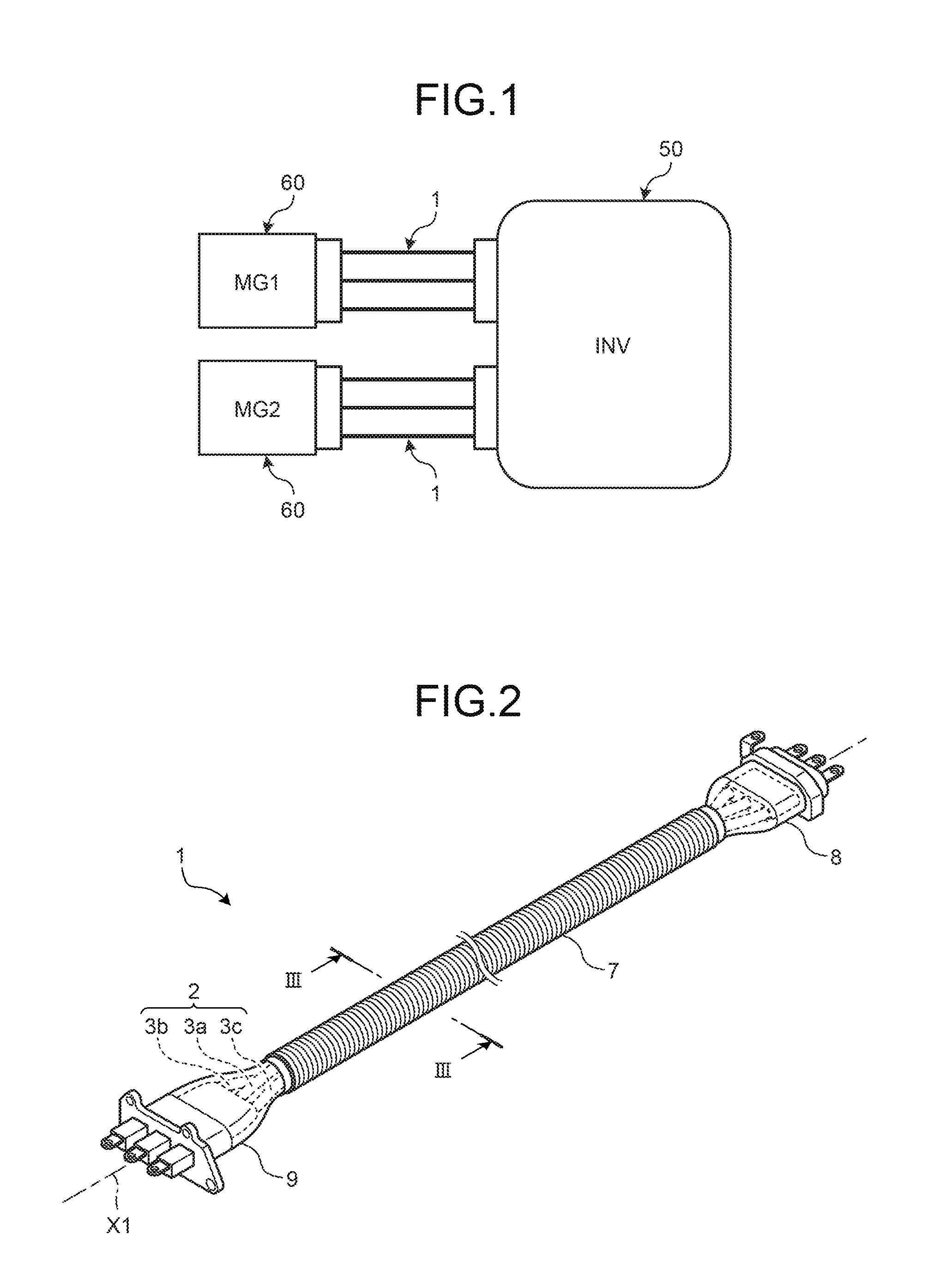
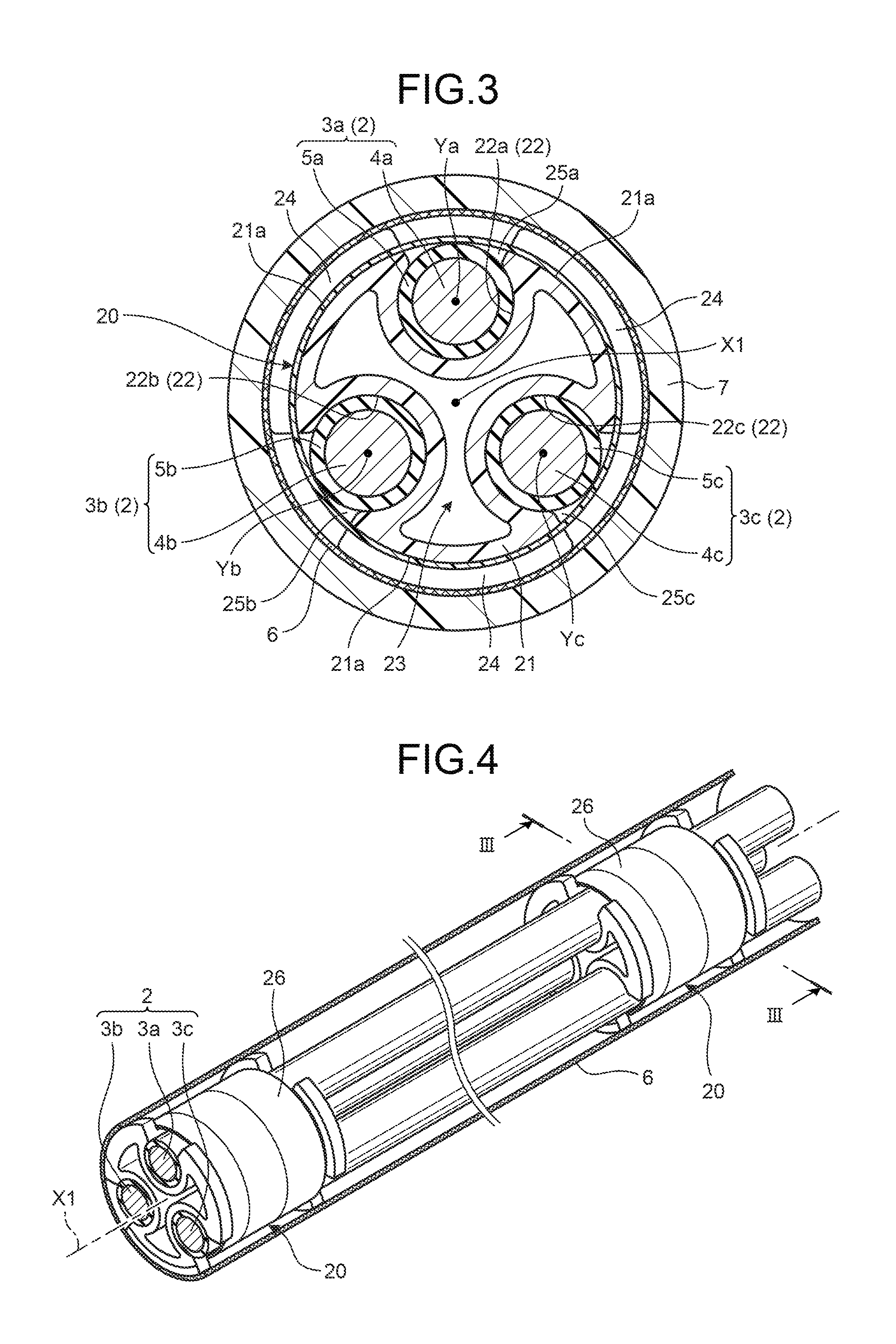
[0024]A configuration of an electric wire holding member 20 and a wire harness 1 according to the present embodiment will be described with reference to FIGS. 1 to 5. FIG. 1 is a schematic diagram illustrating a connection configuration of a motor and an inverter through a wire harness according to an embodiment of the present invention. FIG. 2 is a perspective view of the wire harness according to the embodiment of the present invention. FIG. 3 is a cross-sectional view taken along line III-III in FIGS. 2 and 4, and is an axial cross-sectional view of the wire harness according to the embodiment of the present invention. FIG. 4 is a perspective view illus...


PUM


Abstract

An electric wire holding member (20) includes: a main body portion (21) formed in a cylindrical shape having a central axis line (X1); a plurality of electric wire accommodating portions (22a, 22b, and 22c) provided to penetrate through the main body portion (21) along the central axis line (X1), respectively, and are formed to be capable of individually accommodating electric wires (3a, 3b, and 3c), respectively, the electric wire accommodating portions (22a, 22b, and 22c) being disposed along a circumferential direction around the central axis line (X1) at equal intervals in a cross section as viewed from an axial direction; and a space portion (23) formed between two electric wire accommodating portions adjacent to each other along the circumferential direction to penetrate through the main body portion (21) along the central axis line (X1).

Description

CROSS-REFERENCE TO RELATED APPLICATION(S)[0001]The present application claims priority to and incorporates by reference the entire contents of Japanese Patent Application No. 2015-119642 filed in Japan on Jun. 12, 2015.BACKGROUND OF THE INVENTION[0002]1. Field of the Invention[0003]The present invention relates to an electric wire holding member and a wire harness.[0004]2. Description of the Related Art[0005]In the related arts, an inverter and a motor are connected to each other by three-phase electric wires and electric power is supplied to the motor from the inverter in vehicles such as hybrid vehicles or electric vehicles. In the three-phase wires, a structure to suppress noise by covering collectively the outer periphery by a single braid, a so-called collective shield structure, has been known (for example, see Japanese Patent Application Laid-open No. 2012-249506).[0006]Meanwhile, in the supply of the electric power from the inverter to the motor, the output from the inverter...

Claims


Application Information

Patent Timeline
Patent Type & Authority Applications(United States)
IPC IPC(8): H01B7/00H05K9/00H02G3/04H01B7/17
CPCH01B7/0045H02G3/04H05K9/0086H01B7/17H02G3/0481H05K9/0098
Inventor OHKUBO, YOSHITAKAYAMAGUCHI, YASUHIROMIYAJIMA, TAKAAKIKATO, HAJIMEAIHARA, HIROSHI
Owner YAZAKI CORP
Why Eureka
Try Eureka