Image forming device and image forming control method

A control method and image technology, applied in printing devices, printing, etc., can solve the problems of print quality degradation, lack of correction media, etc., and achieve the effect of suppressing skew

Inactive Publication Date: 2014-12-17
OKI DATA CORP
View PDF10 Cites 3 Cited by
  • Summary
  • Abstract
  • Description
  • Claims
  • Application Information

AI Technical Summary

Problems solved by technology

[0006] However, conventional printers correct the skew of the medium on the way before printing, but do not correct the skew of the medium during printing.
Therefore, especially in printers with a media setting release function, depending on the setting position of the media, skew may occur in subsequent printing executions, resulting in poor print quality

Method used


Image

  • Image forming device and image forming control method
  • Image forming device and image forming control method
  • Image forming device and image forming control method

Examples


Embodiment approach 1

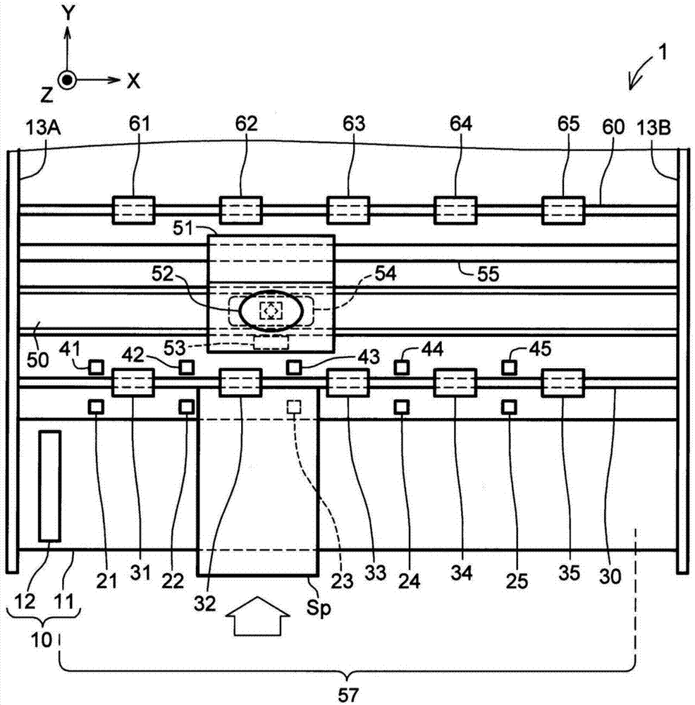
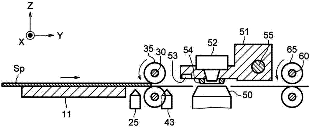
[0047] figure 1 is a diagram schematically showing main mechanisms of the image forming apparatus 1 according to Embodiment 1 of the present invention, figure 2 is viewed from the side figure 1 The mechanism is shown in the diagram. figure 1 and figure 2 The shown X-axis, Y-axis, and Z-axis are perpendicular to each other. The image forming apparatus 1 of the present embodiment has a height in the positive direction of the Z axis, a width in the direction of the X axis, and a depth in the positive direction of the Y axis.

[0048] Such as figure 1 and figure 2 As shown, the image forming apparatus 1 has: side frames 13A, 13B; a space carriage 51 arranged to scan freely in the main scanning direction (X-axis direction); a printing head as a printing part (print recording head) 52 mounted on the space carriage 51; a platen 50 disposed opposite to the print head 52; a table 11 as a medium mounting portion for setting a sheet-shaped to-be-printed medium Sp; a medium s...

Embodiment approach 2

[0127] Next, Embodiment 2 of the present invention will be described. Figure 24 is a diagram schematically showing main mechanisms of the image forming apparatus 2 according to Embodiment 2, Figure 25 is viewed from the side Figure 24 The mechanism is shown in the diagram. Figure 24 and Figure 25 The shown X-axis, Y-axis, and Z-axis are perpendicular to each other.

[0128] Such as Figure 24 and Figure 25 As shown, the image forming apparatus 2 of this embodiment has: a gap lever (gap adjustment mechanism) 67, which is used to adjust the gap interval between the print head 52 and the platen 50 in stages according to the thickness of the medium Sp to be printed; and A gap detection sensor 68 (eg, a transmissive sensor) optically detects the gap interval. Figure 24 and Figure 25 The mechanically acting mechanism shown has the same figure 1 and figure 2 The mechanism shown is the same, but also has a gap lever 67 and a gap detection sensor 68 .

[0129] The c...


PUM


Abstract

Provided are an image forming device and an image forming control method. The invention provides an image forming device capable of inhibiting deflection during an execution process of printing. The image forming device (1) comprises a plurality of medium conveying portions for conveying a printed medium, a medium width detection sensor (53) for detecting the printed medium (Sp), a stability determination portion (71B) for determining whether the conveying stability of the printed medium (Sp) is good according to the relative position of the printed medium (Sp) relative to the plurality of medium conveying portions, a printing control portion (71A) for controlling a control portion (52) and forming printed images on the printed medium (Sp) when the conveying stability is determined to be good, and a reset control portion (71C) for controlling inform portions (91, 92) to inform the information for urging the reset of the printed medium (Sp) when the conveying stability is determined to be not good.

Description

technical field [0001] The present invention relates to a technique for forming a printed image on a printed medium such as paper. Background technique [0002] Generally, a printer has a mechanism for correcting skew (a state in which the medium runs obliquely or in a serpentine state) to be printed on (hereinafter also referred to as “media”). For example, by providing a guide member that restricts the lateral movement of the medium with respect to the conveying direction of the medium, occurrence of skew can be prevented. [0003] In addition, printers are also provided that have a function (hereinafter referred to as "media setting release function") that automatically detects the setting position of the medium and, if it is within the printable form a printed image. For example, a dot matrix printer disclosed in Japanese Patent Application Laid-Open No. 2007-261709 (Patent Document 1) has a medium setting release function and a function of mechanically correcting the ...

Claims


Application Information

Patent Timeline
IPC IPC(8): B41J11/00B41J29/38
Inventor 菊田浩和
Owner OKI DATA CORP
Why Eureka
Try Eureka