Light deflector, optical scanning device and image forming apparatus

An optical deflector and optical deflection technology, which are applied in the electrical recording process using charge patterns, equipment and optics for the electrical recording process applying charge patterns, and can solve the problems of increasing the number of manufacturing processes of optical deflectors and the like

Active Publication Date: 2014-12-17
KYOCERA DOCUMENT SOLUTIONS INC
View PDF3 Cites 9 Cited by
  • Summary
  • Abstract
  • Description
  • Claims
  • Application Information

AI Technical Summary

Problems solved by technology

When the rib is provided on both surfaces of the movable part, a process of providing the rib on one side of the movable part and a process of pro

Method used


Image

  • Light deflector, optical scanning device and image forming apparatus
  • Light deflector, optical scanning device and image forming apparatus
  • Light deflector, optical scanning device and image forming apparatus

Examples


Embodiment Construction

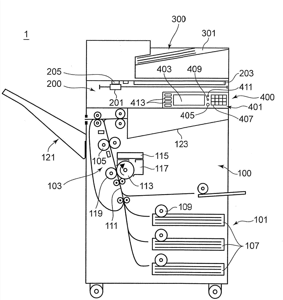
[0025] Hereinafter, embodiments of the present invention will be described in detail with reference to the drawings. figure 1 It is a schematic diagram showing the internal structure of the image forming apparatus 1 using the light deflector according to the present embodiment. The image forming apparatus 1 is applicable to, for example, a digital multifunction machine having a copying function, a printing function, a scanning function, and a facsimile function. The image forming apparatus 1 includes an apparatus body 100 , a document reading unit 200 disposed on the apparatus body 100 , a document supply unit 300 disposed on the document reading unit 200 , and an operation unit 400 disposed on the upper front of the apparatus body 100 .

[0026] The document supply unit 300 functions as an automatic document feeder, and continuously transports a plurality of documents placed on the document placement unit 301 to the document reading unit 200 .

[0027] The document reading u...


PUM


Abstract

A light deflector includes a fixing portion, a movable portion and a reinforcing member. The movable portion includes a mirror portion for deflecting light by swinging about a predetermined swing axis, a torsion bar fixedly supported on the fixing portion and having an axis serving as the swing axis, and a supporting body configured to support the mirror portion and fixed to the torsion bar. The supporting body includes a contact surface to be held in contact with the mirror portion and a non-contact surface opposite to the contact surface. The reinforcing member is provided only on the non-contact surface out of the contact surface and the non-contact surface of the supporting body and reinforces the supporting body and adjusts a center of gravity of the movable portion so that the center of gravity of the movable portion is located on the axis.

Description

technical field [0001] The present invention relates to an optical deflector used for forming electrostatic latent images, etc., an optical scanning device and an image forming apparatus including the optical deflector. Background technique [0002] In an electrophotographic image forming apparatus, a light beam modulated according to image data is generated, reflected and deflected, and the deflected light beam is scanned on an image carrier such as a photosensitive drum to form an electrostatic latent image. Optical deflectors are devices that reflect and deflect light beams. As a light deflector, it has been proposed to use a MEMS (Micro Electro Mechanical Systems) mirror instead of a polygon mirror. MEMS mirrors have advantages such as high-speed scanning and low power consumption. [0003] An optical deflector using a MEMS mirror has a torsion bar, a mirror section that can swing around the axis of the torsion bar, and a mirror drive section. The mirror unit and the ...

Claims


Application Information

Patent Timeline
IPC IPC(8): G02B26/08G02B26/10G03G15/04
CPCG02B26/10G02B26/105G02B26/0858G02B26/125
Inventor 水谷秀次
Owner KYOCERA DOCUMENT SOLUTIONS INC
Why Eureka
Try Eureka