Supercharge Your Innovation With Domain-Expert AI Agents!

Sliding type machine tool punching structure

A punching and machine tool technology, which is applied in the field of machine tool punching mechanism and sliding machine tool punching mechanism, can solve the problems of low automation, poor general performance, and low production efficiency, and achieve high automation, high production efficiency, and structural simple effect

Inactive Publication Date: 2014-12-24
曹雨生
View PDF0 Cites 8 Cited by
  • Summary
  • Abstract
  • Description
  • Claims
  • Application Information

AI Technical Summary

Problems solved by technology

[0005] Beneficial effects of the present invention: In the present invention, since the distance between the fixed punch and the movable punch can be easily adjusted by turning the screw, in one stroke, not only can punch out Two holes, and the distance between the two holes can be adjusted, which is convenient to use in actual production. Therefore, the present invention has the advantages of simple structure, high production efficiency, no need to replace, high degree of automation, and good general performance, effectively overcoming the Existing punching machine tools have the defects of complex structure, low production efficiency, troublesome replacement, low degree of automation, and poor general performance

Method used


Image

  • Sliding type machine tool punching structure

Examples


Embodiment Construction

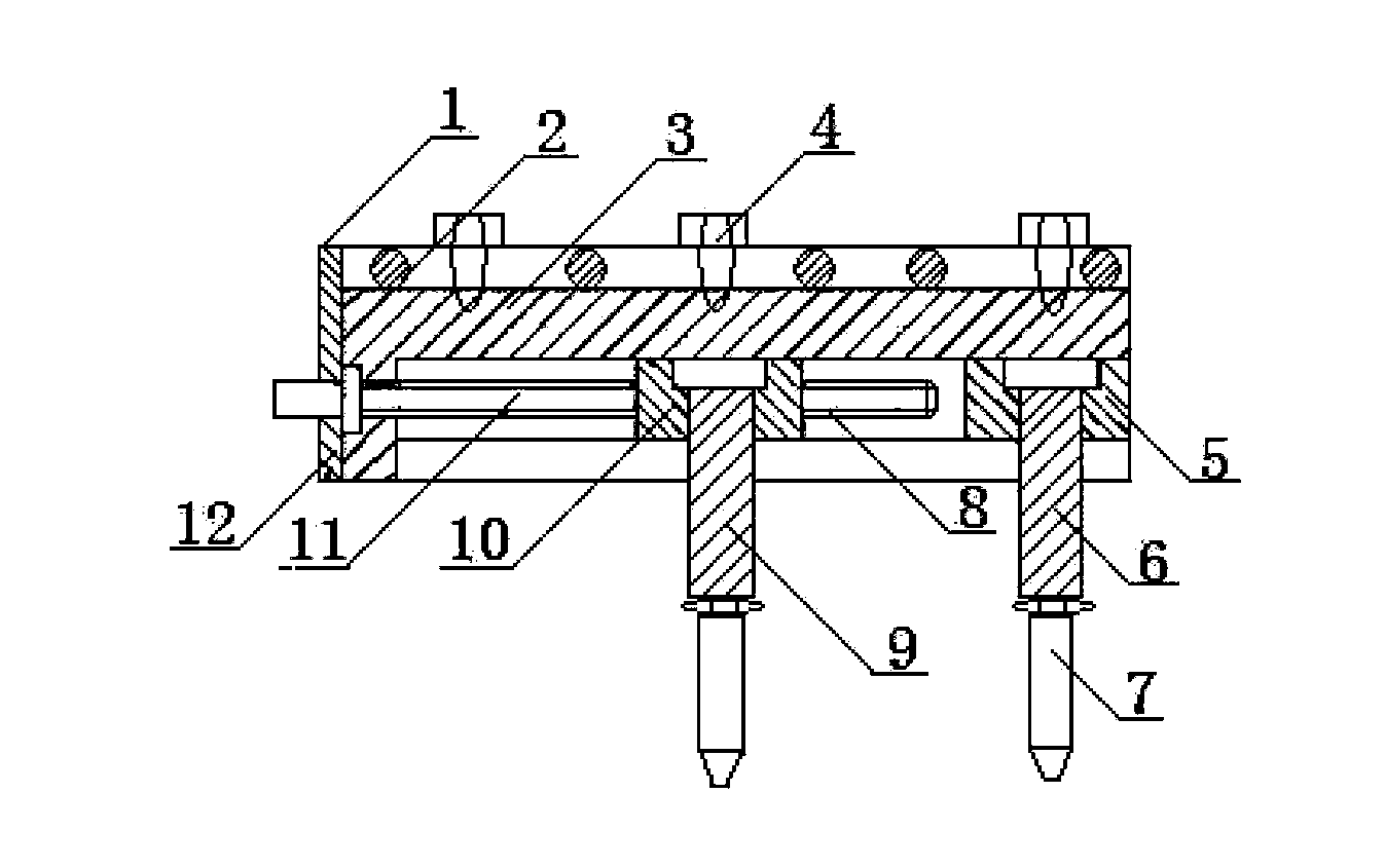
[0009] The punching mechanism of the machine tool has a punching body (3), and the upper end of the punching body (3) is respectively provided with a connecting plate (1), a positioning hole (2) and a fastening bolt (4); A punching slider (10) is installed on the lower end of (3), and a movable punch (9) is arranged on the punching slider (10), and a linear chute is installed on one side of the movable punch (9) ( 8), a splint (5) is installed on the top of the linear chute (8) and the punching body (3), a fixed punch (6) is installed on the splint (5), and a fixed punch (6) is installed There is an adjustable punch (7); a linkage screw (11) is connected to the linear chute (8) on the other side of the movable punch (9), and the linkage screw (11) is connected by the flange (12) fixed.


PUM


Abstract

Disclosed is a sliding type machine tool punching structure. The upper end of a punching machine body is provided with a connecting plate, positioning holes and fastening bolts. A punching sliding block is mounted at the lower end of the punching machine body and provided with a movable male die. A linear slide is made in one side of the movable male die. A clamping plate is arranged at the top end of the linear slide and further arranged on the punching body. A fixed male die is mounted on the clamping plate and provided with an adjustable punch. The other linear slide is formed in the other side of the movable male die and connected to a linkage screw which is fixed with a flange.

Description

technical field [0001] The invention relates to a machine tool punching mechanism, in particular to a sliding type machine tool punching mechanism, which belongs to the technical field of machine tool accessories. Background technique [0002] In the production and manufacture of stamping parts, it is often necessary to punch two holes on the workpiece. At the same time, due to the different specifications and technical requirements of the parts, the distance between the two holes is generally different. At present, in stamping production, in order to To punch out two holes with different hole spacing, a single-process punching mechanism is generally used on the structure of the machine tool, that is, a mechanism that can only punch out one hole in one punch, and the other hole is marked or passed through the corresponding hole. The positioning element is obtained after secondary stamping. Since the required specifications can only be obtained through secondary stamping, it ...

Claims


Application Information

Patent Timeline
IPC IPC(8): B21D28/24
Inventor 曹雨生
Owner 曹雨生
Features
  • R&D
  • Intellectual Property
  • Life Sciences
  • Materials
  • Tech Scout
  • Unparalleled Data Quality
  • Higher Quality Content
  • 60% Fewer Hallucinations
Learn More