Water heater

A technology for water heaters and water pipelines, applied in water heaters, fluid heaters, lighting and heating equipment, etc., can solve the problems of low water preheating efficiency, users need to wait, and water users need to wait, etc., to achieve rapid heating, The effect of increasing efficiency

Inactive Publication Date: 2014-12-24
QINGDAO ECONOMIC & TECHN DEV ZONE HAIER WATER HEATER +1
5 Cites 5 Cited by

AI-Extracted Technical Summary

Problems solved by technology

The problems that exist in this way are: 1. It causes waste of water resources; 2. Hot water cannot flow out directly, and water users need to wait
[0004] The above-mentioned energy-saving water heater preheats the water in the heating coil by preheating, which can effectively shorten the time waiting for hot water t...

Method used

As shown in Figure 1, in this embodiment, the water heater is a gas water heater, which includes a water inlet 101, a water outlet 102, and a water pipeline 103 connected to the water outlet 102, and is located at the water outlet of the water pipeline 103 A water valve 104 is provided; since the existing water heater needs to discharge the cold water in the water pipeline 103 before use, it will cause waste of water resources and require users to wait. To solve this problem, in this embodiment, a heating device 105 is provided on the water pipeline 103, and the heating device 105 is an electric heating wire or an electric heating belt, which is used to heat the water in the water pipeline, so that the user can Hot water can be obtained when the water heater is turned on, which avoids the waste of cold water before and reduces the waiting time of users.
As shown in Figure 2, in this embodiment, temperature sensor 206 is arranged on the water outlet near water pipeline 203, and this kind of setting is because temperature sensor 206 is arranged on the water outlet near water pipeline 203, and it detects The water temperature information is closer to the water temperature to be used by the user, thereby improving the accuracy of controlling the water temperature in the water pipeline 203. In this embodiment, except that the location of the temperature sensor is different from that of the first embodiment, other structures are the same as those of the first embodiment.
As shown in Figure 3, in this embodiment, heating device 305 is to form grid-like structure by electric heating wire with the form of left helix and right helical cross winding, and the heating device 305 of this kind of structure is opposite to water pipeline The heating efficiency of the water in 303 is higher. In this embodiment, except that the structure of the heating device is different from that of the first or second embodiment, other structures are the same as those of the first or second embodiment.
Water heater also comprises control device (not shown), and above-mentioned heating device 105 and temperature sensor 106 are all connected with control device, according to t...

Abstract

The invention discloses a water heater. The water heater comprises water inlets, a water outlet and a water pipeline connected with the water outlet. The water heater further comprises a heating device used for heating water in the water pipeline. The heating device is electric heating wires. The electric heating wires are helically wound outside the water pipeline and can heat stored water in the water pipeline quickly, and the purpose that hot water can flow out when users open a water valve is achieved. Water temperature in the water pipeline can be obtained by setting a temperature sensor on the water pipeline. Meanwhile, the heating device and the temperature sensor are connected with a control device, so that the heating device, the temperature sensor and the control device form feedback adjustment, and water temperature in the water pipeline can be automatically and accurately controlled.

Application Domain

Technology Topic

Image

  • Water heater
  • Water heater
  • Water heater

Examples

  • Experimental program(4)

Example Embodiment

[0027] Implementation mode one
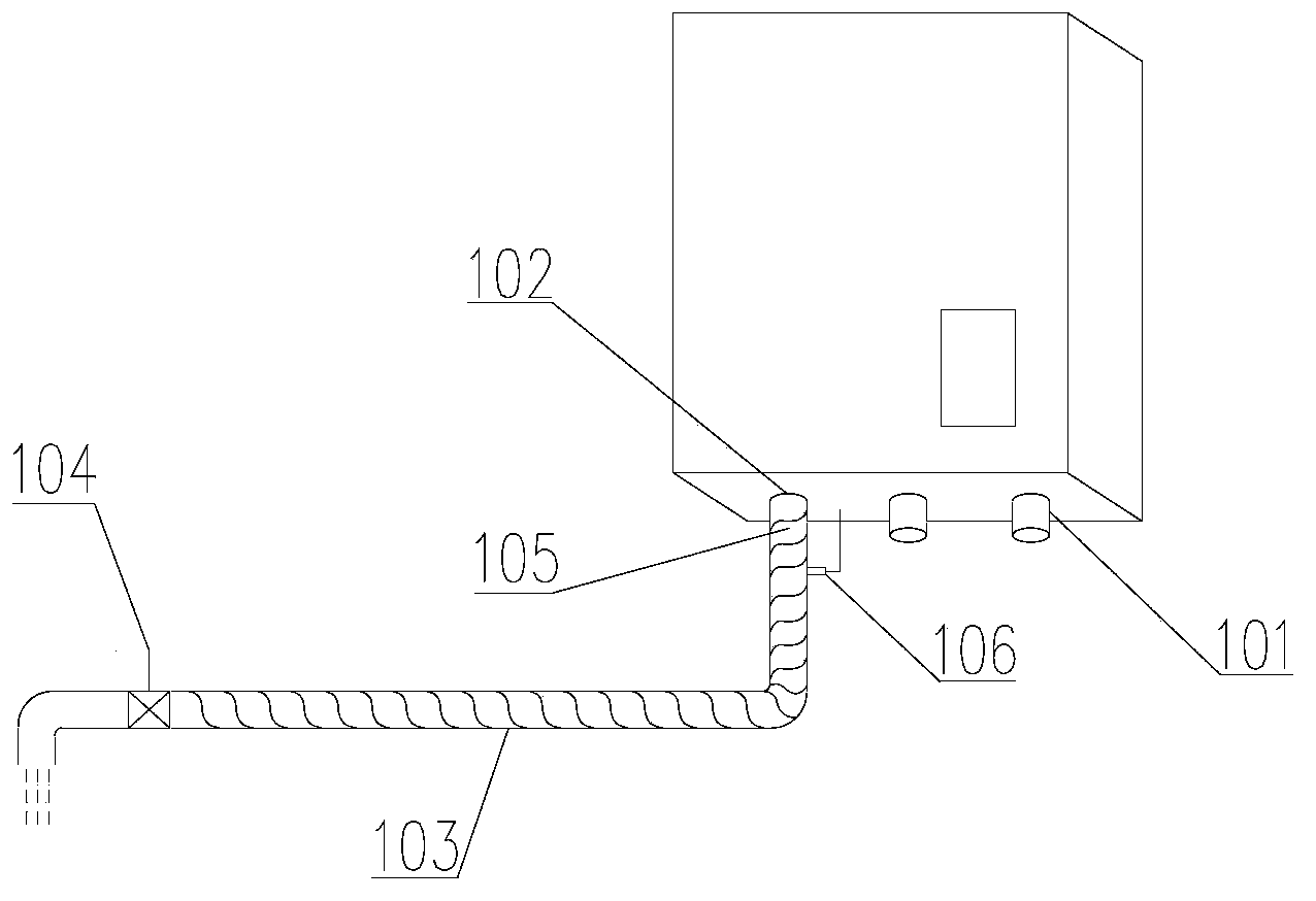
[0028] Such as figure 1 As shown, the water heater in this embodiment is a gas water heater, which includes a water inlet 101, a water outlet 102, and a water pipe 103 connected to the water outlet 102, and a water valve 104 is provided at the water outlet end of the water pipe 103; Since the existing water heater needs to drain the cold water in the water pipe 103 before use, it will cause a waste of water resources and require users to wait. To solve this problem, in this embodiment, a heating device 105 is provided on the water pipe 103. The heating device 105 is an electric heating wire or an electric heating belt, which is used to heat the water in the water pipe so that the user can Hot water is obtained when the water heater is turned on, which avoids the previous waste of cold water and reduces the waiting time for users.
[0029] The above-mentioned electric heating belt is a belt-shaped structure with electric heating wires inside, and the electric heating belt is laid flat or wound on the outside of the water pipe. In this embodiment, an electric heating wire is taken as an example to describe the arrangement and working mode of the heating device. The electric heating wire is spirally wound on the outside of the water pipe 103, specifically, the electric heating wire 103 is wound on the outside of the water pipe in a left-helix or spiral manner.
[0030] In this embodiment, the water pipe 103 is made of heat transfer material, and in order to avoid energy loss in the heat transfer process, the water pipe 103 is wrapped with an insulation layer (not shown), that is, an electric heating wire Set between the water pipeline and the insulation layer. The above-mentioned heat transfer material is thermally conductive silica gel or thermally conductive silicone grease. The water pipeline made of this material can quickly transfer the heat generated by the heating device to the water in the pipeline to heat the water in the pipeline. , And the energy loss is small.
[0031] The above-mentioned water heater further includes a temperature sensor 106 which is arranged on the water pipe 103 for monitoring the water temperature in the water pipe 103.
[0032] The water heater also includes a control device (not shown). The above-mentioned heating device 105 and temperature sensor 106 are both connected to the control device. According to the temperature value of the water that needs to be heated in the water pipe 103 set on the control device, and the temperature detected by the temperature sensor 106 The temperature value controls the opening and closing of the heating device 105. The feedback adjustment system composed of the above-mentioned control device, temperature sensor 106 and heating device 105 can intelligently control the opening and closing of the heating device 105 in real time. While achieving the purpose of heating the water in the water pipe 103, it reduces the use of electric energy. .
[0033] In this application, in order to view the water temperature information in the water pipe intuitively, the above temperature sensor is also connected to the information display screen of the water heater. The information display screen is used to display the temperature information detected by the temperature sensor, which reduces the user's own judgment on the water temperature. It can directly discharge hot water that meets the needs of users.
[0034] In this embodiment, the heating device 105 and the temperature sensor 106 are arranged at the junction of the water outlet 102 and the water pipe 103, and they are arranged at this position to facilitate the installation of the heating device 105 and the temperature sensor 106.
[0035] The working process of the above-mentioned water heater with heat pipe is: after the power is turned on, the heating device 105 works, and the heat will be transferred to the water in the pipe through the water pipe made of heat transfer material, and the heat in the pipe The water is heated. At the same time, the temperature sensor 106 starts to detect the water temperature in the pipeline, and transmits this temperature information to the control device. When the temperature reaches the set value, the control device controls the heating device 105 to turn off to achieve the purpose of preheating the water in the heat pipe; 106 continues to work and transmits the detected water temperature information to the control device. When the water temperature is lower than the temperature set value, the control device controls the heating device 105 to work to achieve the function of keeping the water in the pipeline warm, thereby ensuring When the user opens the water valve, hot water flows out.

Example Embodiment

[0036] Implementation mode two
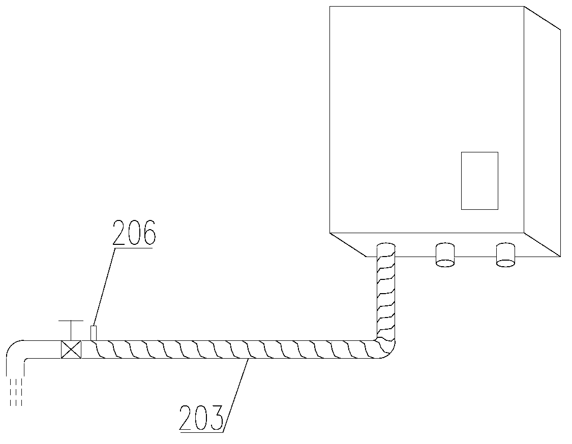
[0037] Such as figure 2 As shown, in this embodiment, the temperature sensor 206 is arranged near the water outlet end of the water pipe 203. Since the temperature sensor 206 is arranged near the water outlet end of the water pipe 203, the detected water temperature information is closer to The water temperature to be used by the user further improves the accuracy of the water temperature control in the water pipe 203. In this embodiment, except that the location of the temperature sensor is different from that of the first embodiment, the other structures are the same as those of the first embodiment.

Example Embodiment

[0038] Implementation mode three
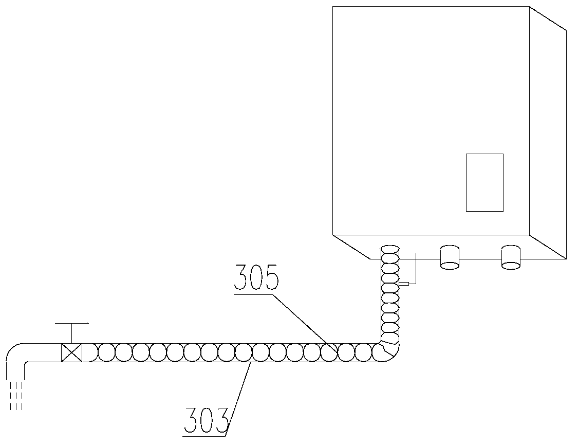
[0039] Such as image 3 As shown, in this embodiment, the heating device 305 is formed by an electric heating wire in a form of cross-wound left and right spirals to form a grid structure. The heating device 305 of this structure heats the water in the water pipe 303 higher efficiency. In this embodiment, except that the structure of the heating device is different from the first or second embodiment, the other structures are the same as those of the first or second embodiment.

PUM

no PUM

Description & Claims & Application Information

We can also present the details of the Description, Claims and Application information to help users get a comprehensive understanding of the technical details of the patent, such as background art, summary of invention, brief description of drawings, description of embodiments, and other original content. On the other hand, users can also determine the specific scope of protection of the technology through the list of claims; as well as understand the changes in the life cycle of the technology with the presentation of the patent timeline. Login to view more.

Similar technology patents

Control of exhaust gas purification system

InactiveCN106907222AIncrease exhaust temperatureHeating fastHybrid vehiclesInternal combustion piston enginesHybrid driveElectricity
Owner:FORD GLOBAL TECH LLC

Plate local heating device and heating method thereof

InactiveCN106475475AHeating fastRapid local heatingShaping toolsPower flowControl unit
Owner:NAT KAOHSIUNG UNIV OF SCI & TECH

Classification and recommendation of technical efficacy words

  • Heating fast
  • Improve efficiency
Why Eureka
Try Eureka