An active anti-stealing device and a method for compensating and measuring strong magnetic electricity theft

A technology of stealing electricity and strong magnetism, applied in the direction of measuring devices, measuring electrical variables, measuring time integration, etc., can solve the problems of poor timeliness, electric energy measurement errors, and many measuring equipment, and achieves complete and practical noise, reduces test errors, and design. reasonable effect

Active Publication Date: 2018-01-12
STATE GRID CORP OF CHINA +2
View PDF11 Cites 0 Cited by
  • Summary
  • Abstract
  • Description
  • Claims
  • Application Information

AI Technical Summary

Problems solved by technology

[0005] (1) The power grid anti-stealing device is mainly for single protection of the 0.4KV user-side metering device, such as a special counter, load control device or remote meter reading system, and because there are many means of stealing electricity, any device for a single means of stealing electricity obviously cannot Meet the requirements, and the existing anti-stealing devices do not have the function of compensating for under-measured electricity, and manual calculation is required;
[0006] (2) The traditional inspection mainly relies on manual business census, which has poor timeliness and insufficient census. It is difficult to grasp the operation status of the distribution network in real time, and it is impossible to accurately provide the time, place and related data of the electricity theft, making it difficult to verify;
[0007] (3) The existing distribution network has a complex structure and many metering equipment, so real-time monitoring and recording cannot be achieved. When some high-tech methods are used to steal electricity, the existing equipment and measures are helpless
For example, a constant strong magnetic field close to the CT leads to electricity stealing means of energy measurement errors;

Method used


Image

  • An active anti-stealing device and a method for compensating and measuring strong magnetic electricity theft
  • An active anti-stealing device and a method for compensating and measuring strong magnetic electricity theft

Examples


Embodiment

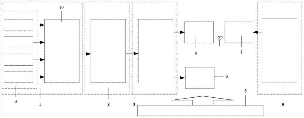
[0042] Such as figure 1 As shown, an active anti-theft device of the present invention includes a front-end signal acquisition module 1, a power theft determination and identification module 2, a main control module 3, a communication module 4, a power supply module 5, an output action module 6, and a remote The end database 8 (host computer), etc., in this example is for a three-phase four-wire electric energy meter.

[0043] Front-end signal acquisition module 1, install a magnetic sensor (using Hall element) on the CT part of the electric energy meter, install current and voltage transformers to monitor the line current and line voltage in the user's incoming and outgoing lines, and install an optical switch at the opening of the meter box The circuit leads the signal from the electric energy meter to monitor the working status of the electric energy meter, and finally sends the signal collected above to the signal conditioning circuit. The signal conditioning circuit converts ...


PUM


Abstract

The invention discloses an active electricity larceny prevention device and a method aiming at magnetic electricity larceny compensation metering. The device comprises a front-end data collecting module, a signal processing circuit, an electricity larceny behavior judging and identifying module. If behaviors are judged to be electricity larceny behaviors, different treatment measures are adopted according to electricity larceny measures. Especially, when magnetic electricity larceny is performed, compensation metering needs to be performed on the magnetic electricity larceny due to the fact that the magnetic electricity larceny is high in imperceptibility and restores to the normal state when interference is removed so as to facilitate inspection. The steps of the method aiming at magnetic electricity larceny compensation metering is showed in the picture below. By the device and the method, the intelligence level and automation level of the active electricity larceny prevention device are increased greatly, key inspection and evidence obtaining by inspectors are facilitated, and corresponding treatment can be performed timely.

Description

Technical field [0001] The patent of the invention relates to the field of online monitoring and electric energy measurement, and relates to an active anti-theft device and a compensation measurement method for strong magnetic power theft. Background technique [0002] In recent years, the power grid has developed rapidly, and the power consumption of individuals and businesses has increased dramatically. Facing the ever-increasing demand for electricity, some illegal enterprises and individuals, in order to seek economic benefits, illegally connect and modify electric energy metering equipment to achieve the purpose of stealing electricity. According to a country’s conservative statistics, the amount of electricity stolen in a country is at least 2 billion kilowatt-hours per year. Based on the average electricity price of 0.4 yuan, the direct economic loss amounts to more than 800 million yuan. This does not include the repair of damaged meters, wiring and other equipment. cost...

Claims


Application Information

Patent Timeline
Patent Type & Authority Patents(China)
IPC IPC(8): G01R11/24G01R11/17
Inventor 王冬云浦小玲卢海涛杨涛郭小进黄民发林红刚邢智
Owner STATE GRID CORP OF CHINA
Why Eureka
Try Eureka