
Detection system capable of automatically switching detection voltage and voltage calibration detection method of detection system capable of automatically switching detection voltage

A detection system and automatic switching technology, which is applied in the field of detection systems to achieve the effect of automatic switching, reducing manpower and testing time, and reducing the rate of human error judgment

Active Publication Date: 2014-12-24
INVENTECSHANGHAI TECH +2
View PDF6 Cites 1 Cited by
  • Summary
  • Abstract
  • Description
  • Claims
  • Application Information

AI Technical Summary

Problems solved by technology

[0008] In view of the above-mentioned problems in the prior art, the purpose of the present invention is to provide a detection system capable of automatically switching the detection voltage and its voltage calibration detection method to solve the problem of using a power supply when performing ADC Calibration on an existing graphic computing device. The problem of inputting the test voltage required by the graphics computing device through manual switching

Method used


Image

  • Detection system capable of automatically switching detection voltage and voltage calibration detection method of detection system capable of automatically switching detection voltage
  • Detection system capable of automatically switching detection voltage and voltage calibration detection method of detection system capable of automatically switching detection voltage

Examples


Embodiment Construction

[0030] In order to facilitate your examiners to understand the technical features, content and advantages of the present invention and the effects it can achieve, the present invention is hereby combined with the accompanying drawings, and described in detail in the form of embodiments as follows, and the accompanying drawings used therein, Its purpose is only for illustration and auxiliary instructions, not necessarily the true proportion and precise configuration of the present invention after implementation, so the scale and configuration relationship of the attached drawings should not be interpreted to limit the scope of rights of the present invention in actual implementation .

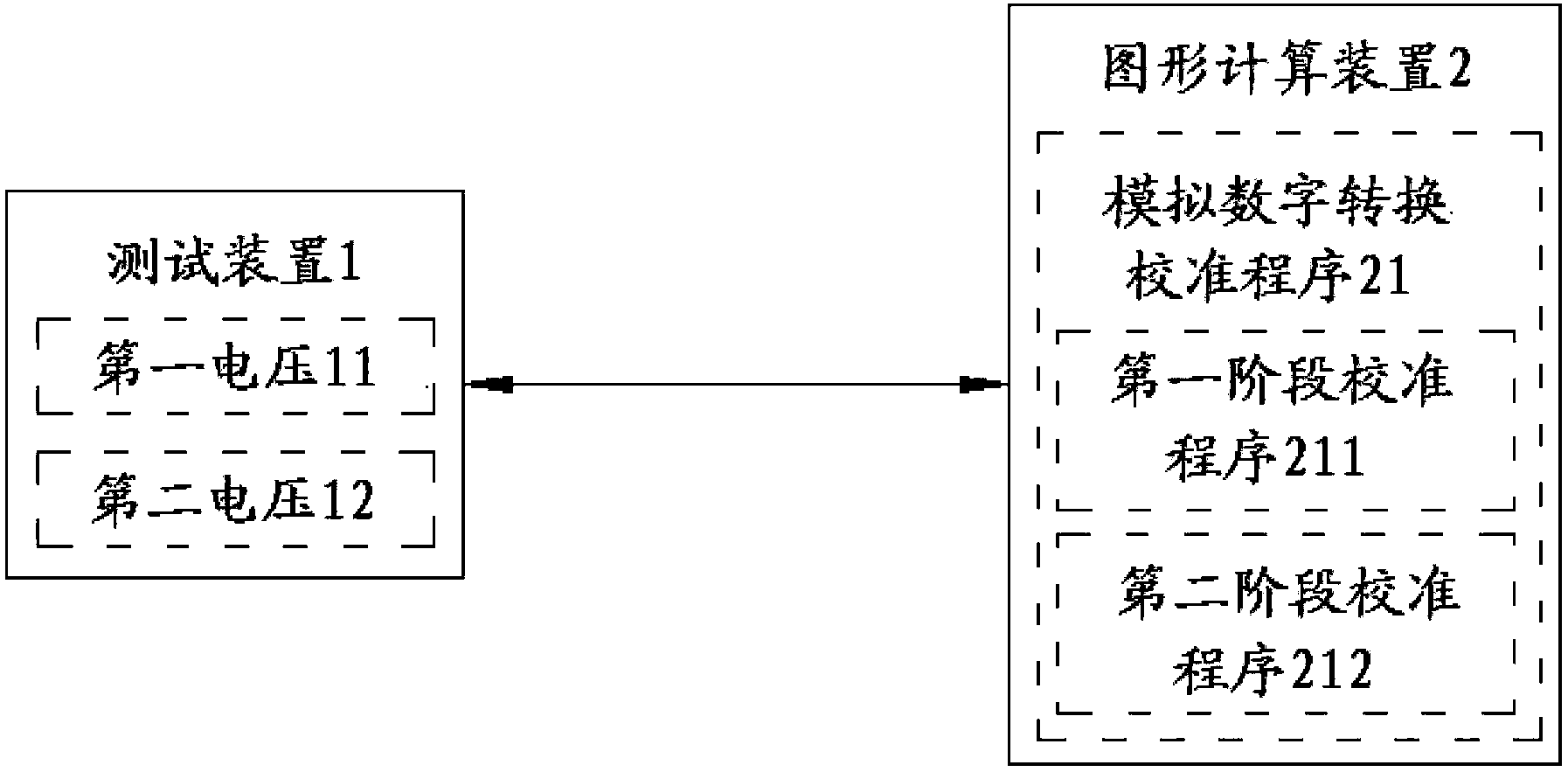
[0031] see figure 1 , which is a block diagram of a detection system capable of automatically switching detection voltages of the present invention. In the figure, the detection system capable of automatically switching the detection voltage includes a testing device 1 and a graphics computing ...


PUM


Abstract

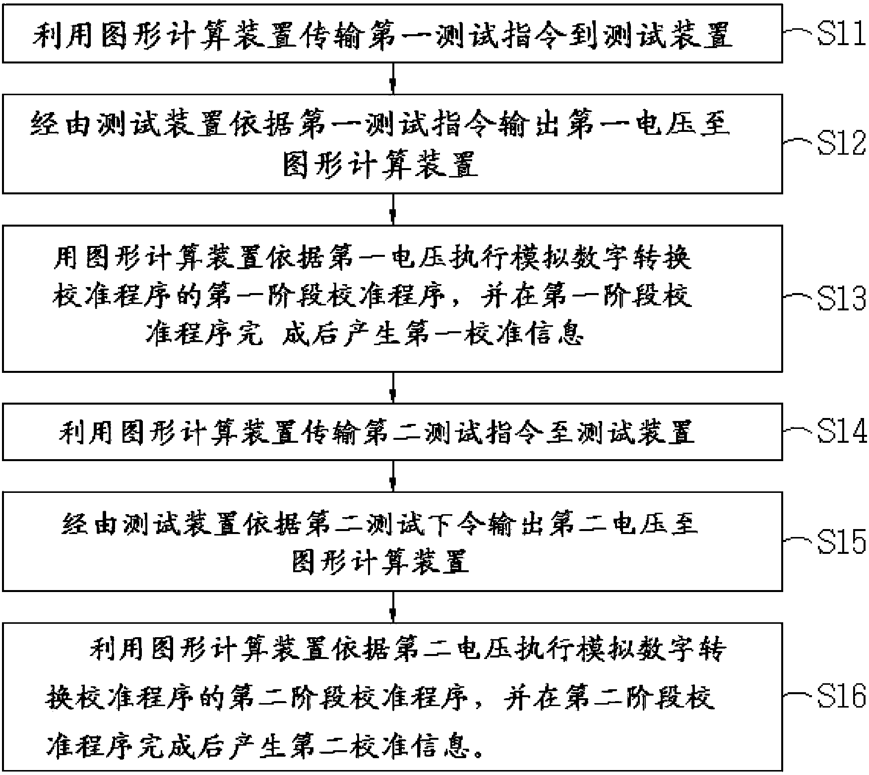
The invention discloses a detection system capable of automatically switching the detection voltage and a voltage calibration detection method of the detection system capable of automatically switching the detection voltage. The detection system comprises a testing device and a graph calculation device. The testing device can selectively output a first voltage and a second voltage. When executing an analog digital conversion calibration procedure, the graph calculation device transmits a first testing command to the testing device to receive the first voltage output by the testing device according to the first testing command and execute a first-stage calibration procedure, and transmits a second testing command to the testing device to receive the second voltage output by the testing device according to the second testing command and execute a second-stage calibration procedure. The analog digital conversion calibration procedure includes the first-stage calibration procedure and the second-stage calibration procedure.

Description

technical field [0001] The invention relates to a detection system and method, in particular to a detection system capable of automatically switching detection voltages and a voltage calibration detection method thereof. Background technique [0002] Graphing calculator (Nspire) models are in production, ADC Calibration needs to sample ADC through two voltages of 3.0 volts (v) and 4.0 volts (v), and use software to convert ADC calculations through formulas Generate a voltage, and then judge the detection information of the result (pass or fail). Finally, the synthesis of the detection information of the 3.0v and 4.0v test results can finally determine whether the ADC Calibration has passed or failed. [0003] In the current existing test methods, the detection of ADC Calibration is realized by manually switching the 3.0v and 4.0v respectively provided by the two channels of the power supply. However, this manual method of detection has the following disadvantages: [0004...

Claims


Application Information

Patent Timeline
Patent Type & Authority Applications(China)
IPC IPC(8): G01R31/00G01R35/00
Inventor 邱春艳朱经纬陈世松
Owner INVENTECSHANGHAI TECH
Learn More