Universal type rotor core overlaying tool and method

A rotor core and stacking tooling technology, applied in the field of rotor core stacking, can solve the problems of increasing the time of the rotor core stacking process, increasing the working stroke of the hydraulic press, and reducing production efficiency, so as to shorten the operating hours and increase the production efficiency. Large compression area, the effect of improving production efficiency

Active Publication Date: 2014-12-24
安徽金箔机电产业集团股份有限公司
View PDF5 Cites 11 Cited by
  • Summary
  • Abstract
  • Description
  • Claims
  • Application Information

AI Technical Summary

Problems solved by technology

[0003] 1. The closing sleeve needs to be removed before it can be placed into the fixed key at the end of the rotor core. At this time, the rotor core is no longer under pressure and the core should be loose;
[0004] 2. The tooling of the closed structure must be higher than the end face of the motor shaft before the rotor core can be laminated. On the one hand, it is easily limited by the stroke of the hydraulic press, and on the other hand, the working stroke of the hydraulic press is increased, thereby increasing the process of laminating the rotor core. time, reducing production efficiency;
[0005] 3. The direct use of columnar steel to press the rotor core requires manual pre-fixing, placement and removal one by one, which increases the time of the rotor core lamination process, reduces production efficiency, and reduces the safety factor in the manufacturing process

Method used


Image

  • Universal type rotor core overlaying tool and method
  • Universal type rotor core overlaying tool and method
  • Universal type rotor core overlaying tool and method

Examples


Embodiment Construction

[0029] The present invention will be further described below in conjunction with non-limiting examples.

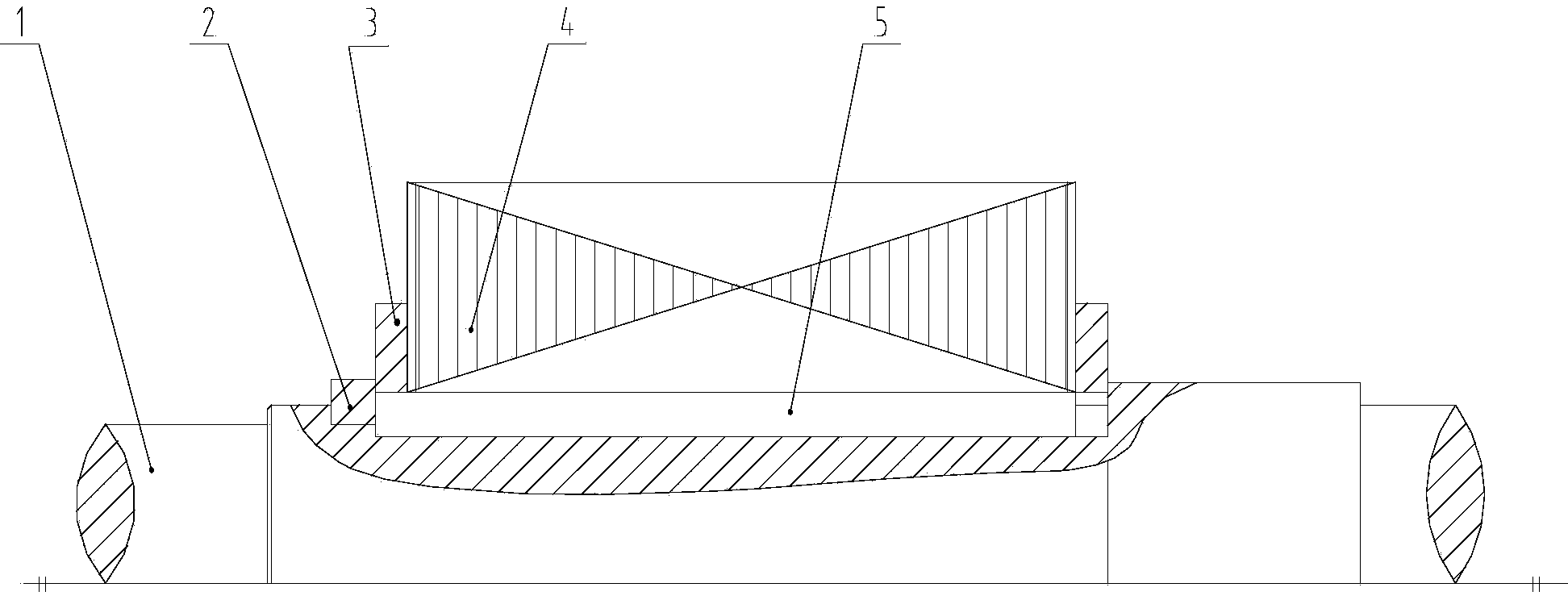
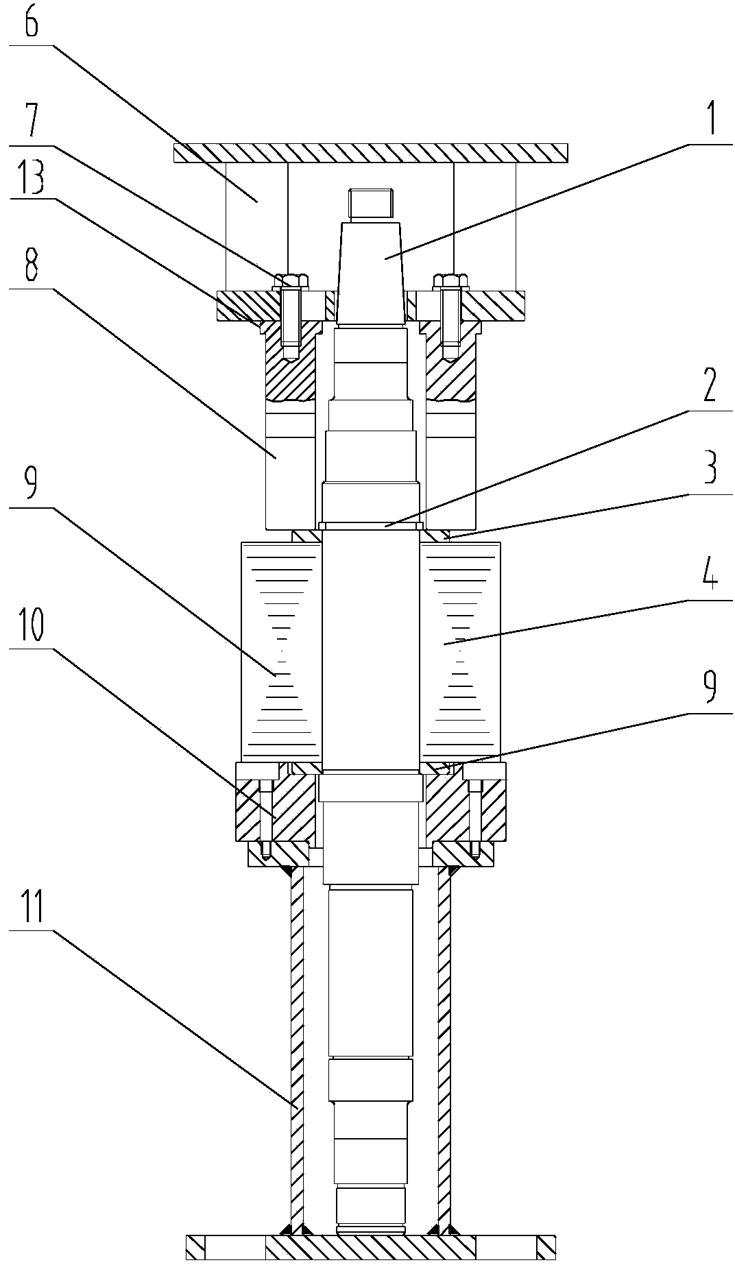
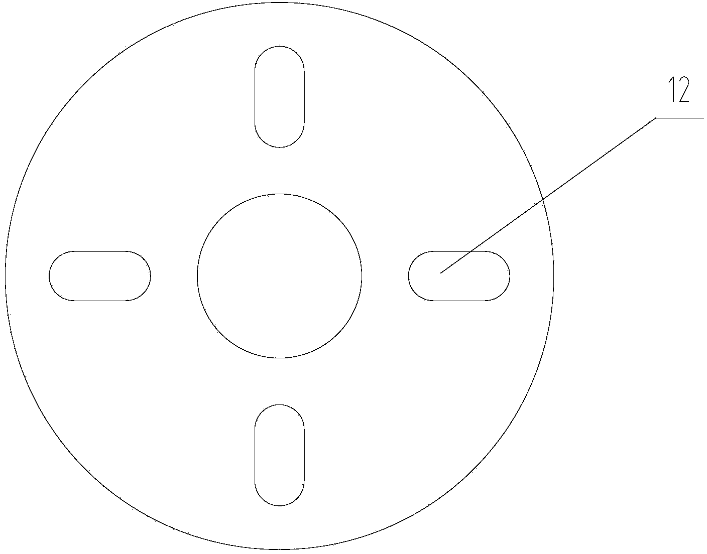
[0030] As shown in the figure: the general-purpose rotor core lamination tooling of the present invention includes a pressure applying part and a pressure receiving part, the mandrel 1 is located between the pressure applying part and the pressure receiving part, and the mandrel 1 is fixed by the rotor core key 5 The rotor core 4; the pressure exerting parts include a pressure table 6 and a pressure column 8, the pressure table 6 and the pressure column 8 are connected through the waist hole 12 and the fixing bolt 7, and the top of the pressure column 8 has a boss 13; the pressure bearing parts include a base 11, The base transition plate 10, the upper rotor retainer 3, the lower rotor retainer 9, the upper and lower ends of the rotor iron core 4 are installed with the rotor retainer, the upper rotor retainer 3 is installed with the fixed key 2 at the end of the rotor core,...


PUM


Abstract

The invention discloses a universal type rotor core overlaying tool which comprises a platen, a base and a mandrel. The mandrel is sleeved with rotor cores in an overlaid mode. The rotor cores are located between the platen and the base, and core laminations are overlaid through the platen and the base jointly. The universal type rotor core overlaying tool is characterized in that a plurality of pressing columns are connected with the lower portion of the platen and are evenly and annularly distributed at intervals, and the platen drives the pressing columns to enable the iron laminations to be overlaid. According to the universal type rotor core overlaying tool, the pressing column structure is adopted, and radial clearances exist between the pressing columns; compared with a traditional closed overlaying tool, rotor core end fixing keys can be installed when the rotor cores are compressed, the influences of the oil press stroke on rotor core overlaying specifications can be lowered, the security coefficients in the rotor core overlaying process are increased, working procedure tome is shortened, and production efficiency is improved by about 30%.

Description

technical field [0001] The invention relates to the technical field of rotor iron core lamination, in particular to a general-purpose rotor iron core lamination tool and lamination method. Background technique [0002] For motor manufacturers that produce rotors in China, many of the lamination work of the rotor core is carried out on the motor shaft. In order to achieve the lamination coefficient of the rotor core, a closed sleeve, closed ring bracket or columnar steel corresponding to the model and specification of the motor is usually made, and then the core is compressed by a hydraulic press. These types of laminated tooling usually have the following defects: [0003] 1. The closing sleeve needs to be removed before it can be placed into the fixed key at the end of the rotor core. At this time, the rotor core is no longer under pressure and the core should be loose; [0004] 2. The tooling of the closed structure must be higher than the end face of the motor shaft bef...

Claims


Application Information

Patent Timeline
Patent Type & Authority Applications(China)
IPC IPC(8): H02K15/02
Inventor 王安华朱学峰
Owner 安徽金箔机电产业集团股份有限公司
Why Eureka
Try Eureka