Motor

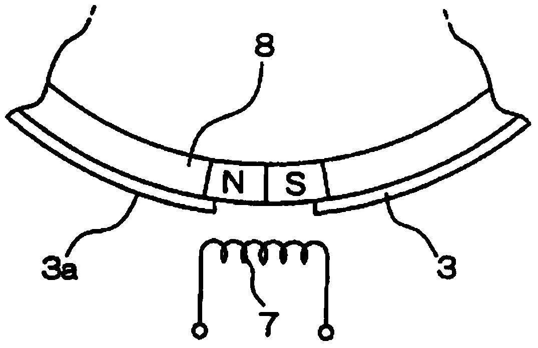
A motor and cage technology, applied in the field of motors, can solve the problems of low operation efficiency, reduction of magnetic flux in external space, shortened distance between rotor magnet 8 and induction body 7, etc.

Inactive Publication Date: 2014-12-24
NIDEC CORP
View PDF6 Cites 3 Cited by
  • Summary
  • Abstract
  • Description
  • Claims
  • Application Information

AI Technical Summary

Problems solved by technology

[0003] However, the above conventional motors have the following technical problems: (1) the detection position is deviated due to the divergence of the magnetic flux; Because the magnetic flux of 8 is absorbed by the rotor yoke 3, the magnetic flux in the external space will be reduced, so the distance between the rotor magnet 8 and the induction body 7 needs to be shortened; (3) Since the rotor yoke 3 is provided with a hole 3b, The magnetic flux of the rotor magnet 8 leaks, and the motor characteristics will deteriorate; (4) When the rotor magnet 8 is fixed on the inner periphery of the flange 3 a of the rotor yoke 3 , since the outer periphery of the rotor magnet 8 cannot be coated and bonded (5) When assembling the rotor magnet 8 and the rotor yoke 3, it is necessary to mark the magnetic pole switching part on the rotor magnet 8 and make the magnetic pole switching part of the rotor magnet 8 from Hole 3b is exposed, resulting in low work efficiency

Method used


Image

  • Motor
  • Motor
  • Motor

Examples


Embodiment Construction

[0020] Those skilled in the art will appreciate that the drawings in the specification are schematic and not necessarily drawn to scale. The terms "inner", "outer", "upper" and "lower" used herein are for convenience of description. In addition, the following embodiments are only examples of the present invention, and the scope of protection of the present invention is not limited thereto, but shall be determined by the claims.

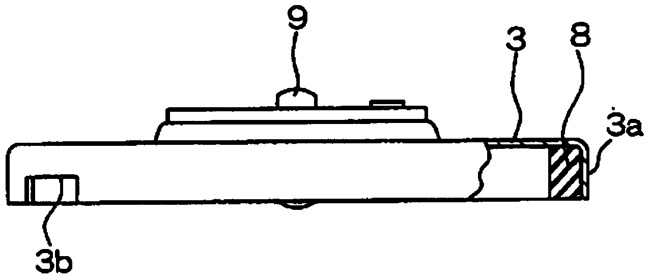
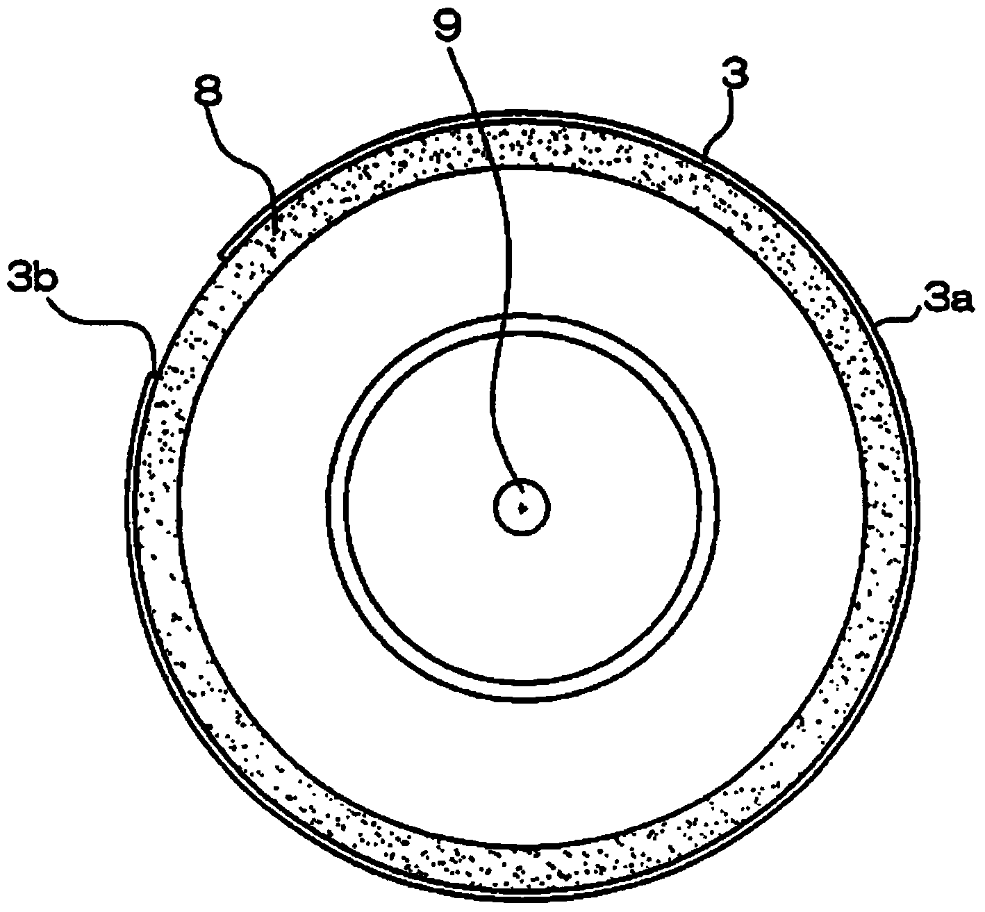
[0021] Figure 4 shows a cross-sectional view of a first embodiment of the motor of the present invention; Figure 5 show Figure 4 Schematic side view of the motor; Image 6 show Figure 4 Another schematic side view of the motor. In this manual, for the convenience of explanation, refer to Figure 4 , the direction along the central axis OO' is defined as the axial direction, the radial direction centered on the central axis OO' is defined as the radial direction, and the circumferential direction centered on the central axis OO' is defined as...


PUM


Abstract

A motor comprises a rotating body and a static body, wherein the rotating boy is supported to be capable of rotating relative to the static body with the central axis as the center. The rotating body comprises a rotor holder with a cylindrical side wall, a rotor magnet fixed to the inner circumferential face of the side wall of the rotor holder, and three or more consecutive alternate magnetic poles, wherein the alternate magnetic poles are arranged on a circumferential local part of the rotator holder and exposed outwards in the radial direction. The static body comprises a magnetism position detecting mechanism which is located on the radial outer side of the side wall of the rotor holder, and the magnetism position detecting mechanism can detect the rotating position of the rotor holder. The alternate magnetic poles are arranged in the mode that when the rotating body rotates to a specific area, the alternate magnetic poles and the magnetism position detecting mechanism can be oppositely arranged in the radial direction, and the magnetism position detecting mechanism detects the rotating position of the rotor holder by detecting the magnetic pole switching parts of the alternate magnetic poles. Due to the fact that the alternate magnetic poles are arranged, the deviation of the detecting position can be avoided.

Description

technical field [0001] The invention relates to a motor, especially a motor whose rotational position needs to be detected during use. Background technique [0002] In many electronic devices that include a motor, such as floppy disk drives that include a motor for driving a floppy disk and digital light processing (DLP) projectors that include a motor for driving a color wheel, it is desirable to detect the rotational position of the motor. For example, Chinese patent document CN1179344C discloses a motor in which the position of the rotating body is detected by using an inductor to detect the magnetic flux of the rotor magnet. like Figure 1-2 As shown, the rotor yoke 3 of this motor is formed as a cup with a shallow overall depth, and a flange 3a is integrally provided on its peripheral portion, and a notch-shaped hole 3b of a predetermined width is formed in a part of the flange 3a. In addition, the rotor yoke 3 is provided with a shaft 9 penetrating through its center....

Claims


Application Information

Patent Timeline
Patent Type & Authority Applications(China)
IPC IPC(8): H02K29/08
Inventor 李鹏张东旭
Owner NIDEC CORP
Why Eureka
Try Eureka