
Integrated soil-tilling apparatus for rotary ploughs

A technology of turning plows, land, applied in the direction of plows, applications, shovels, etc., which can solve the problem of weakening the longitudinal frame structure costs, etc.

Active Publication Date: 2014-12-24
LEMKEN
View PDF9 Cites 3 Cited by
  • Summary
  • Abstract
  • Description
  • Claims
  • Application Information

AI Technical Summary

Problems solved by technology

Additional joints in the longitudinal frame weaken the longitudinal frame or require additional construction costs

Method used


Image

  • Integrated soil-tilling apparatus for rotary ploughs
  • Integrated soil-tilling apparatus for rotary ploughs
  • Integrated soil-tilling apparatus for rotary ploughs

Examples


Embodiment Construction

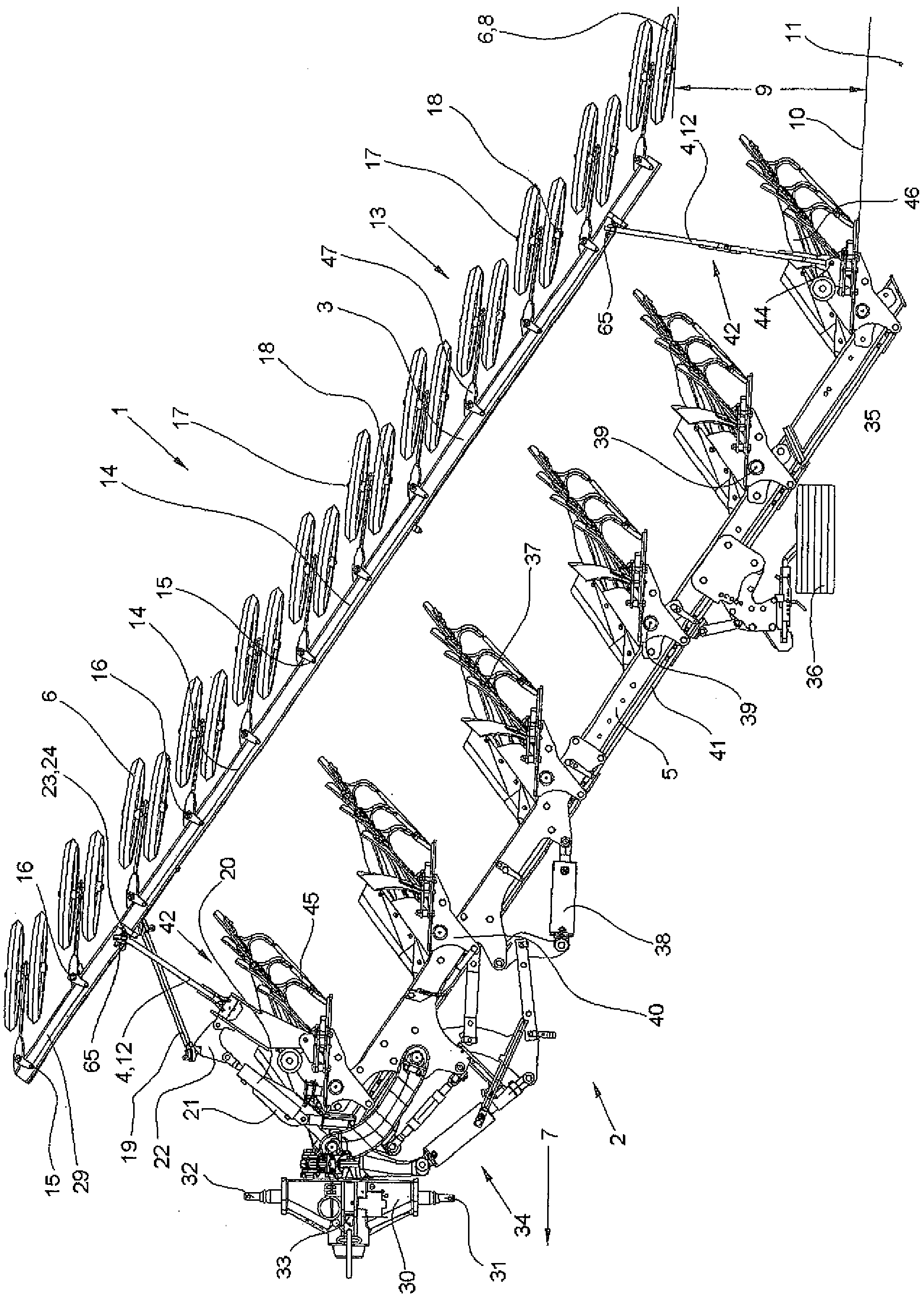
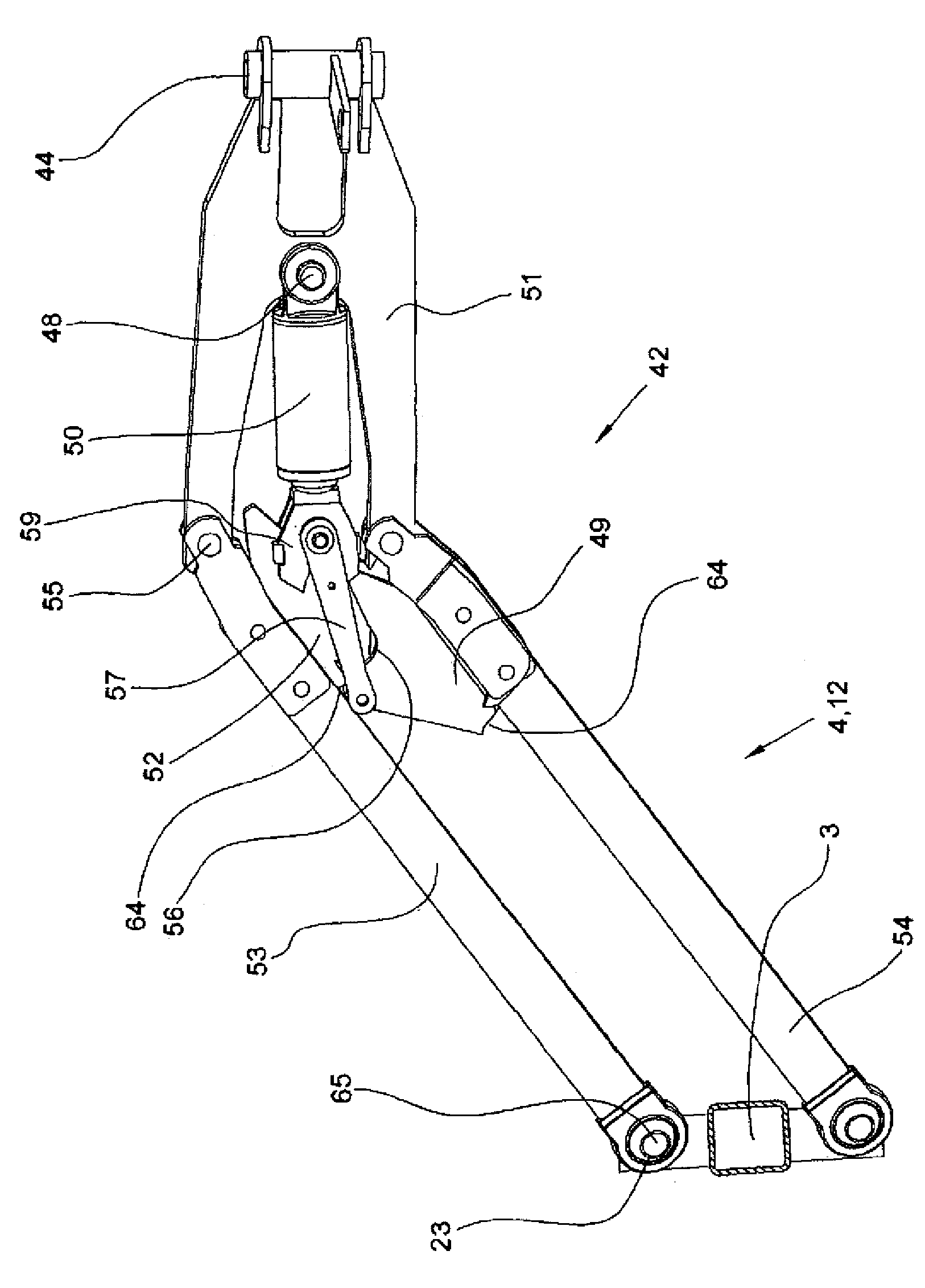
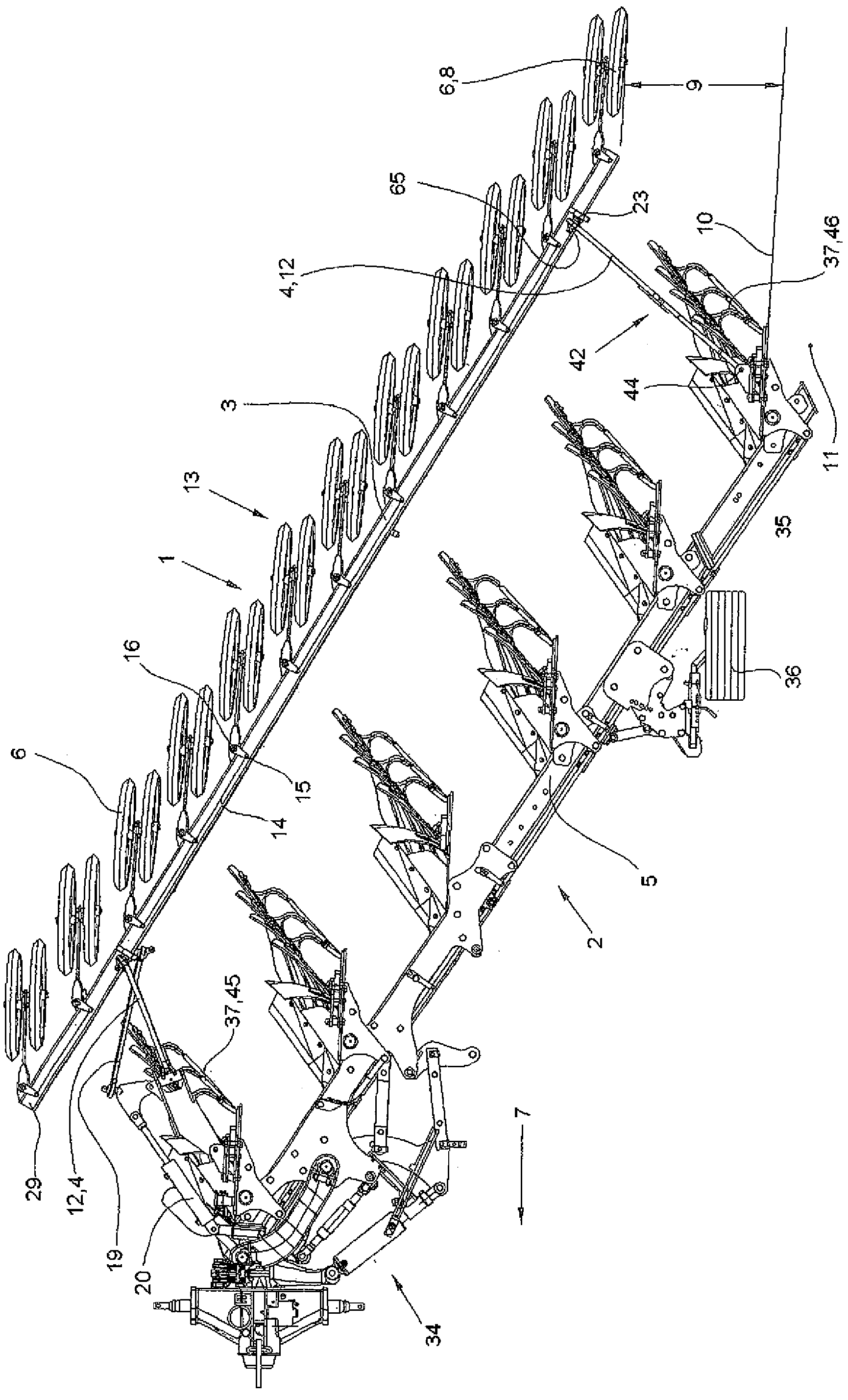
[0011] figure 1 Shown is a reversing plow 2 which, with its plow turret 30, can be connected via articulation points 31, 32 and 33 to a three-point tie rod (not shown) of a tractor and which has support wheels in the rear area 35 36. The tilting plow 2 has a link drive 34 with which in particular the front furrow width and the point of application of the tension can be adjusted and the plow frame 5 swiveled inwards, although this is not discussed further below in the description of the figures. The tilting plow 2 also has a plow frame 5 , to which the plow body 37 is fixed indirectly via a pivot bracket 40 and which can be adjusted in its working width about an axis of rotation 39 . The adjustment of the working width of the plow body 37 and thus the working width of the entire tilting plow 2 is effected by means of the hydraulic cylinder 38 . Here, the pivot brackets 40 of the individual plow bodies 37 are connected to one another via control rods 41 . Pivot bearings 44 ar...


PUM


Abstract

The invention relates to an integrated soil-tilling apparatus (1), the longitudinal frame (3) of which is connected to a reversible plough (2) via converging connecting rods (4) and which is pivotable into a working position having a favourable centre of gravity and into a position for the first furrow at the field edge. The convergence of the connecting rods (4) is selected such that for the first furrow the front part of the integrated soil tilling apparatus (1) is pivoted in rearwards to the reversible plough (2) and the rear part of the integrated soil tilling apparatus (1) assumes in both positions approximately the same distance from the furrow edge of the last plough body of the reversible plough (2). Via an adjusting centre (42) having a double-acting hydraulic cylinder (50), the integrated soil-tilling apparatus (1) can be brought into a secure fixed central position for the reversing operation and, during work, can be brought onto the soil with a pre-set supporting force into a soil-crumbling or soil-consolidating working position.

Description

technical field [0001] The invention relates to an integrated soil tillage device (Bodenbearbeitungsgeröt) for a tilting plow (Drehpflüge) according to the preamble of claim 1 . Background technique [0002] An integrated soil tillage device for a turning plow is a device attached and carried at the turning plow that works the plowed ground of the turning plow and turns on the turning front part (Vorgewende, sometimes called the field border) During the process and also for transport routes on roads and streets, the turning plow can remain. During operation, the device must not be decoupled before the diversion process and must not be caught again after the diversion process and must not be transported separately for the transport route. Such an integrated soil tillage device usually has measures in which it is achieved that the integrated soil tillage device is not disturbed for the first pass or the first furrow at the edge of the cultivated field, that is, it is swiveled...

Claims


Application Information

Patent Timeline
IPC IPC(8): A01B17/00
CPCA01B3/464A01B17/004A01B49/02
Inventor W. 米尔斯
Owner LEMKEN
Learn More