Novel complete polarization temperature-changing source device of microwave radiometer

A microwave radiometer and full polarization technology, which is applied in radiation pyrometry, measuring devices, optical radiation measurement, etc., can solve problems such as poor frequency compatibility, difficult control of the temperature of the calibration body, and complex calibration equation algorithms, etc., to achieve The temperature change time is short, which is beneficial for spaceborne applications and convenient for testing

Active Publication Date: 2015-01-07
NAT SPACE SCI CENT CAS
View PDF5 Cites 10 Cited by
  • Summary
  • Abstract
  • Description
  • Claims
  • Application Information

AI Technical Summary

Problems solved by technology

[0005] The purpose of the present invention is to solve the problems that the calibration temperature of the calibration body is not easy to control, or the calibration equation algorithm is complicated and the frequency compatibility is poor in the existing calibration technology of the fully polarized microwave radiometer. The present invention provides a new type of omnipolar The variable temperature source device of the microwave radiometer is replaced by the phase retarder in the present invention figure 1 The phase retardation plate in simplifies the scaling equation; at the same time, because the phase retarder with a polarization grid has good broadband performance, the phase retarder has high frequency compatibility, and the phase retarder introduced by the phase retarder The calibration error of the

Method used


Image

  • Novel complete polarization temperature-changing source device of microwave radiometer
  • Novel complete polarization temperature-changing source device of microwave radiometer
  • Novel complete polarization temperature-changing source device of microwave radiometer

Examples


Embodiment Construction

[0030] A new type of fully polarized microwave radiometer variable temperature source device according to the present invention will be described in detail below in conjunction with the accompanying drawings and embodiments.

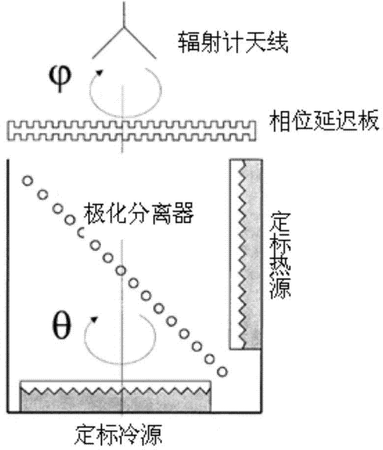
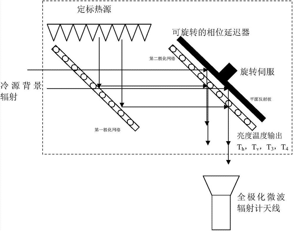
[0031] Such as figure 2 As shown, the new full-polarization microwave radiometer variable temperature source device includes: a calibration heat source, a calibration cold source, a first polarization grid and a phase retarder. The plane where the calibration heat source is located is perpendicular to the plane where the calibration cold source is located, and the first polarization grid is located between the calibration cold source and the calibration heat source and is at an angle of 45 degrees to the horizontal plane; The relative positions between the calibration heat source, the calibration cold source and the first polarization grid are fixed, and the phase retarder is set to rotate around the central axis perpendicular to the plane where it is l...


PUM


Abstract

The invention provides a novel complete polarization temperature-changing source device of a microwave radiometer. The device comprises a calibrating heat source, a calibrating cold source, a first polarization grid and a phase delayer, wherein a plane where the calibrating heat source is located and a plane where the calibrating cold source is located are in perpendicular mutually, and the first polarization grid is located between the calibrating cold source and the calibrating heat source and forms an angle of 45 degrees with a horizontal plane; relative positions among the calibrating heat source, the calibrating cold source and the first polarization grid are fixed; the phase delayer is arranged in a rotating manner by using a center shaft perpendicular to a plane where the phase delayer is located as a center. Only through the rotation of the phase delayer which consists of a second polarization grid and a plane reflecting plate, the temperature-changing source device can achieve the purpose of changing and outputting brightness and temperature. The temperature of the calibrating heat source is fixed, the temperature is simple to control, the angle of the phase delayer is easy to control, and the precision is higher, so that the device has high temperature changing output stability, the purpose of changing the temperature can be achieved in a shorter time, and the complete polarization calibrating temperature-changing source has stable output.

Description

technical field [0001] The invention relates to the technical field of microwave radiometer calibration, in particular to a novel fully polarized microwave radiometer variable temperature source device. Background technique [0002] Microwave (including millimeter wave and submillimeter wave) radiometer is a passive microwave remote sensor, which is used to observe global atmospheric temperature and humidity, water vapor content, rainfall and other space weather data all day and all day, as well as ocean surface temperature , ocean wind field, soil moisture and other information, which play an important role in atmospheric detection and ocean observation. [0003] The fully polarimetric microwave radiometer is a new type of passive microwave remote sensor, which can measure four Stokes parameters of a target at one time, and is another powerful means of extracting target features. The traditional external calibration methods of microwave radiometers use two-point calibratio...

Claims


Application Information

Patent Timeline
Patent Type & Authority Applications(China)
IPC IPC(8): G01J5/52G01J5/60
Inventor 王振占王新彪刘璟怡陆浩李彬张升伟
Owner NAT SPACE SCI CENT CAS
Why Eureka
Try Eureka