
A Gradient Coil Used in Magnetic Resonance Imaging

A technology of magnetic resonance imaging and gradient coils, which is applied in the direction of measuring magnetic variables, measuring devices, instruments, etc., can solve the problems of wasting space and increasing manufacturing costs, and achieves the effect of reducing manufacturing costs and meeting the needs of human body scanning.

Active Publication Date: 2017-12-15
XBO MEDICAL SYST
View PDF11 Cites 0 Cited by
  • Summary
  • Abstract
  • Description
  • Claims
  • Application Information

AI Technical Summary

Problems solved by technology

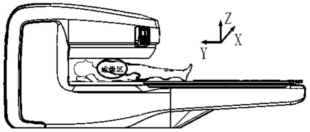
The imaging area of ​​the existing MRI system is designed to be circular, although this can meet the requirements of the imaging range in the Y direction, but a part of the space in the X direction is wasted, which increases the manufacturing cost

Method used


Image

  • A Gradient Coil Used in Magnetic Resonance Imaging
  • A Gradient Coil Used in Magnetic Resonance Imaging
  • A Gradient Coil Used in Magnetic Resonance Imaging

Examples


Embodiment

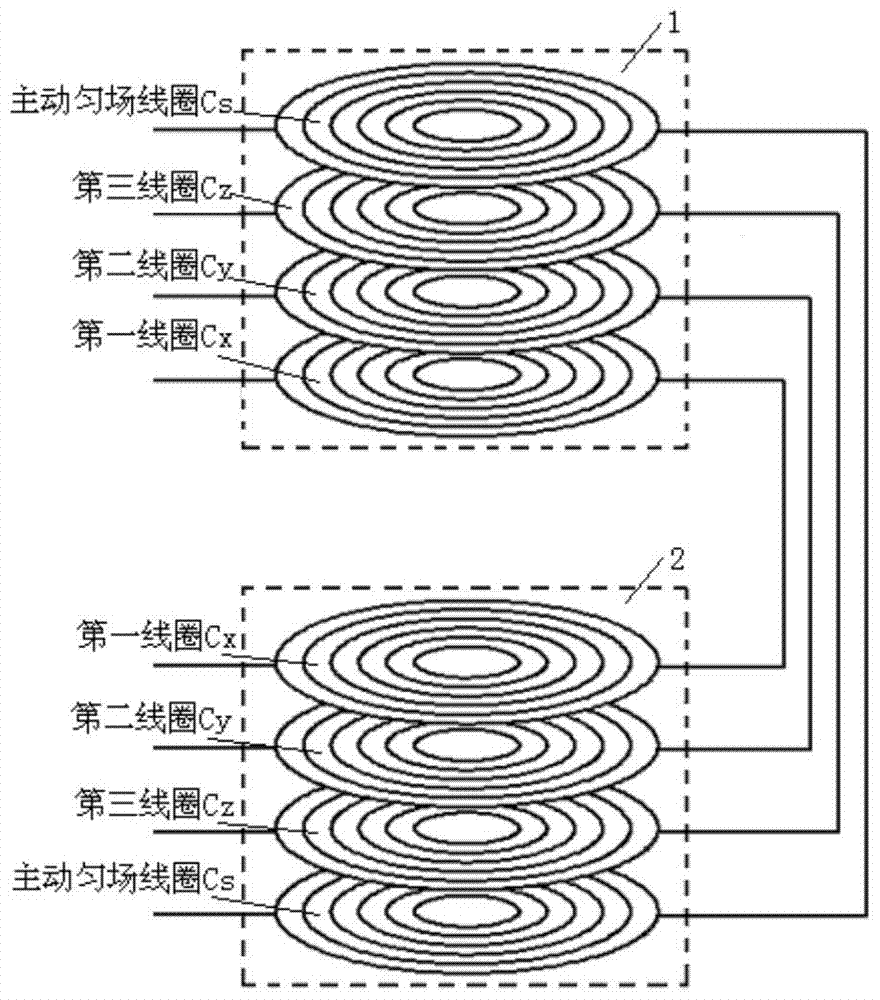
[0028] Embodiment: First, a conventional gradient coil is designed by using the current density method, and the length of the imaging area in the Y direction is equal to the length in the X direction. Secondly, taking the second coil Cy in the first main coil 1 and the second main coil 2 as an example, as Figure 5 As shown, the length of the second coil Cy is stretched along its Y direction, and the ratio of the length Ly of the coil in the Y direction to the length Lx in the X direction is 1.14. Finally, using the separated wire method to calculate the change of the gradient field after the stretching of the second coil Cy, and fine-tuning the second coil Cy according to the change of the gradient field, the following is obtained: Image 6 coil shown. For the first coil Cx, the third coil Cz and the active shim coil Cs, the same method as that of the second coil Cy is used for processing. Wherein, the coil sizes of the first coil Cx, the third coil Cz and the active shim c...


PUM


Abstract

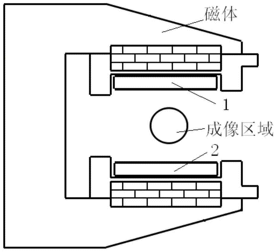
The invention relates to a gradient coil used in magnetic resonance imaging, which is characterized in that it includes first and second main coils, and the first and second main coils each include a first coil Cx, a second coil Cy, a third coil The coil Cz, the active shim coil Cs and the insulating layer, the first coil Cx, the second coil Cy, the third coil Cz and the active shim coil Cs are sequentially arranged in parallel in the same vertical plane, the first coil Cx and the second An insulating layer is provided between the coils Cy, between the second coil Cy and the third coil Cz, and between the third coil Cz and the active shim coil Cs; when the first and second main coils are mounted on the magnet together, the first In series with the same coils in the second main coil, the shapes of the first coil Cx, the second coil Cy, the third coil Cz and the active shim coil Cs are all set to be elliptical, and the first and second main coils cooperate to obtain an ellipsoidal imaging area.

Description

technical field [0001] The invention relates to a gradient coil, in particular to a gradient coil used in magnetic resonance imaging. Background technique [0002] Magnetic Resonance Imaging (MRI) equipment is one of the greatest inventions of the last century. It can be used to scan almost every part of the human body. It has no ionizing radiation damage to the human body, and the soft tissue structure is clearly displayed. It can be used for disease diagnosis in various parts of the body. . Gradient coil is an important part of MRI equipment. It is mainly used to generate linear gradient magnetic fields in three directions, perform layer selection, phase encoding and frequency encoding on MRI signals, and provide positioning basis for image reconstruction. The development of MRI technology puts forward higher requirements on the performance of gradient coils, so it is very meaningful to optimize the design and structure of gradient coils. [0003] like figure 1 As shown...

Claims


Application Information

Patent Timeline
Patent Type & Authority Patents(China)
IPC IPC(8): G01R33/385
Inventor 王振刘景顺孟洪卫杨杰
Owner XBO MEDICAL SYST
Learn More