
Special measuring clamp for imager centre type impeller

A technology for measuring fixtures and imagers, which is applied in the direction of manufacturing tools, workpiece clamping devices, etc., can solve the problems of low precision, inability to meet the requirements of imager scanning and impeller positioning, etc., and achieve the effect of high concentricity

Inactive Publication Date: 2020-11-03
MAANSHAN FANGYUAN POWER TECH
View PDF0 Cites 0 Cited by
  • Summary
  • Abstract
  • Description
  • Claims
  • Application Information

AI Technical Summary

Problems solved by technology

[0005] At present, the fixtures on the market are mainly for ordinary impellers, and the accuracy is low, which cannot meet the needs of imager scanning and impeller positioning.

Method used


Image

  • Special measuring clamp for imager centre type impeller
  • Special measuring clamp for imager centre type impeller
  • Special measuring clamp for imager centre type impeller

Examples


Embodiment Construction

[0027] specific implementation plan

[0028] In order to facilitate the understanding of the present invention, the present invention will be described more fully below with reference to the associated drawings. Preferred embodiments of the invention are shown in the accompanying drawings. However, the present invention can be embodied in many different forms and is not limited to the embodiments shown herein. On the contrary, the purpose of providing these embodiments is to provide a more comprehensive and thorough understanding of the disclosure of the present invention.

[0029] It should be noted that when an element is said to be "fixed on" or "placed on", it can be placed directly on another element or there can be an intermediate element. When an element is described as being "connected to" another element, it can be directly connected to the other element by some means or intervening elements may also be present. As used herein, the terms "one end," "the other end,"...


PUM


Abstract

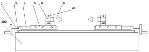
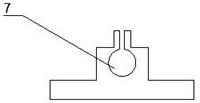
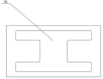
The invention provides a special clamp for an imager centre type impeller. The special clamp comprises a base, wherein an I-shaped through hole is formed inside the base, and the base is placed on animager after the surface of the base is ground by a lathe; a dovetail groove supporting plate with the surface ground by the lathe is fixed on the base, a rectangular through hole is formed inside thedovetail groove supporting plate, and a first threaded hole is formed in one side of the dovetail groove supporting plate; a screw rod is arranged inside the dovetail groove supporting plate, and thescrew rod penetrates through the dovetail groove supporting plate through the rectangular through hole and the first threaded hole; a positioning block is arranged on the screw rod, a second threadedhole is formed in the positioning block, and the positioning block is connected with the screw rod through the second threaded hole; the positioning block is connected with a dovetail groove slidingtable with the surface ground by the lathe; the dovetail groove sliding table is connected with a centre fastening part with the bottom surface ground by the lathe, the centre fastening part is in aninverted-T shape, and a through hole is formed in the upper half portion of the centre fastening part; the centre fastening part is connected with a centre through the through hole; and the whole clamp is arranged on the base in a bilateral symmetry mode.

Description

technical field [0001] The present application relates to the field of mechanical manufacturing, in particular to a special measurement fixture for a thimble impeller of an imager. [0002] technical background [0003] The thimble fixture of the imager refers to the device that uses the thimble to fix the processing object in the process of mechanical manufacturing, so that the processing object is in the correct position, so that the fixed workpiece can be scanned and detected by the imager. [0004] Scanning the workpiece by the imager requires the workpiece to be in a highly horizontal position on the X-Y coordinate system, and the fixture needs to be able to accurately position and clamp the workpiece. [0005] At present, the fixtures on the market are mainly for ordinary impellers, and the accuracy is low, which cannot meet the needs of imager scanning and impeller positioning. Contents of the invention [0006] The invention provides a high-precision fixture that c...

Claims


Application Information

Patent Timeline
Patent Type & Authority Applications(China)
IPC IPC(8): B25B11/00
CPCB25B11/00
Inventor 朱玉亮董金山郑有为何芳
Owner MAANSHAN FANGYUAN POWER TECH
Learn More