Automatic welding production line and automatic welding method for wire coils

An automatic welding and production line technology, applied in welding equipment, welding equipment, auxiliary welding equipment, etc., can solve the problems of low production efficiency and low degree of automation, improve production efficiency and degree of automation, reduce production costs, and increase clamping The effect of holding strength

Active Publication Date: 2015-05-20
佛山市慧智智能装备有限公司
View PDF12 Cites 18 Cited by
  • Summary
  • Abstract
  • Description
  • Claims
  • Application Information

AI Technical Summary

Problems solved by technology

Another object of the present invention is to provide a wire reel automatic welding method, thereby replacing the traditional manual welding process, reducing labor intensity and improving production efficiency, while ensuring the wire reel welding quality and solving the problem of low automation and low production efficiency in the current welding industry The problem is suitable for mass production for intelligent manufacturing of wire reels

Method used


Image

  • Automatic welding production line and automatic welding method for wire coils
  • Automatic welding production line and automatic welding method for wire coils
  • Automatic welding production line and automatic welding method for wire coils

Examples


Embodiment 1

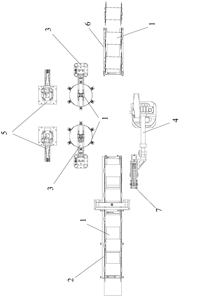
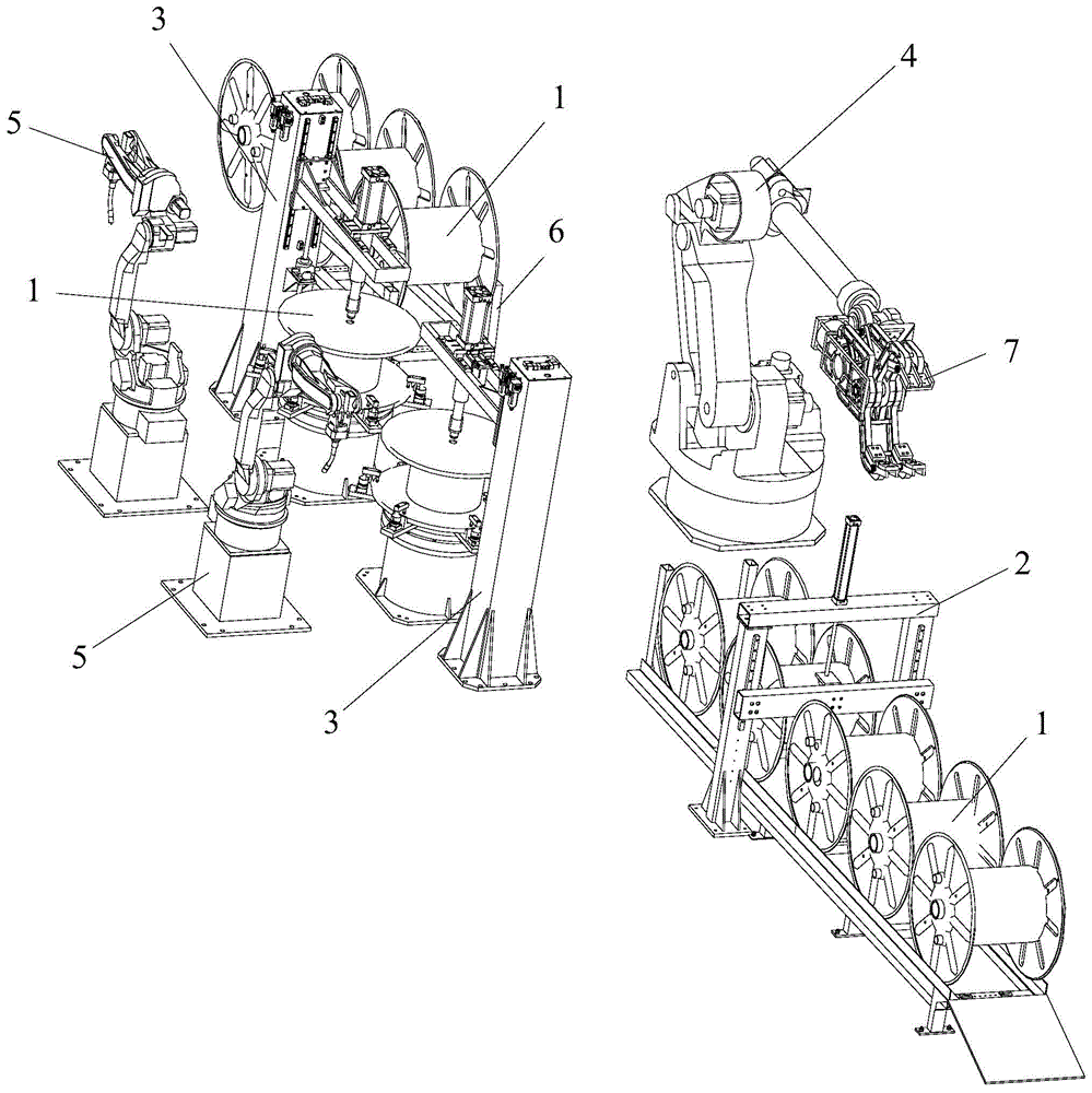
[0054] Such as Figure 1 to Figure 9 As shown, the wire reel automatic welding production line of the present invention is used for welding the wire reel 1, which includes a feed conveying mechanism 2 for separating and conveying the wire reel 1; for positioning and rotating the wire reel 1 The compression positioning mechanism 3; is used to grab the wire reel 1 from the feed conveying mechanism 2, and the wire reel 1 is transported and placed on the compression positioning mechanism 3 for welding. The handling manipulator 4; The welding manipulator 5 for welding the wire reel 1 on the 3; the discharge conveying mechanism 6 for transferring the wire reel 1; Control mechanism for signal connection.

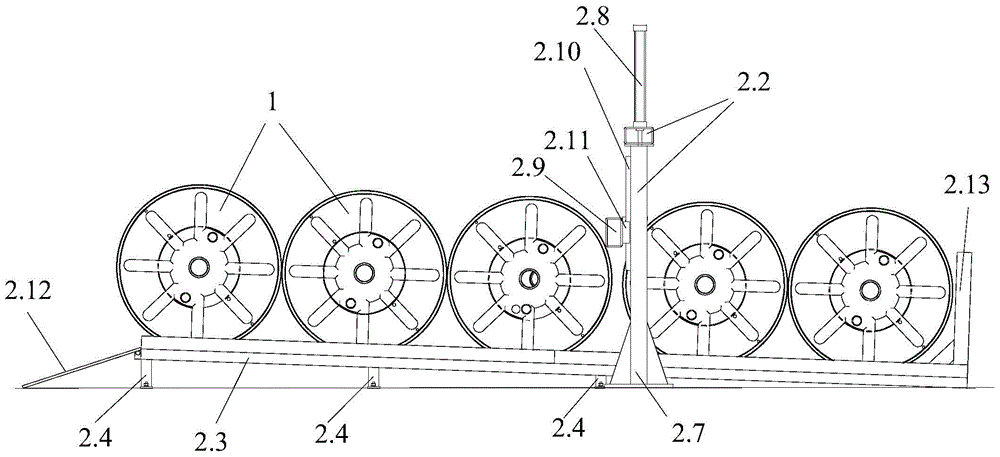
[0055] Such as image 3 and Figure 4 As shown, wherein, the feeding conveying mechanism 2 includes a transmission line and a separation device 2.2 for separating the transmission between the wire reels 1 so as to facilitate the subsequent operation of a single wire reel 1, wher...

Embodiment 2

[0082] The only difference between this embodiment and Embodiment 1 is that the two clamping arms can be set to a single-layer structure, a three-layer structure or a structure with more than three layers, and in the clamping arms with a three-layer structure or a structure with more than three layers , each structure is connected by connecting rods. The design of the multi-layer structure of the clamping arm can increase the contact area between the clamping arm and the workpiece, thereby further improving the clamping force of the clamping device.

[0083] Other structures of this embodiment are consistent with Embodiment 1.


PUM


Abstract

The invention provides an automatic welding production line for wire coils. The production line comprises a feeding and conveying mechanism, a pressing and positioning mechanism, a transferring manipulator, a welding manipulator, a discharging and conveying mechanism and a control mechanism in signal connection with the feeding and conveying mechanism, the pressing and positioning mechanism, the transferring manipulator and the welding manipulator. The production line is simple in structure, high in welding speed and high in welding quality stability, the phenomenon that welding of welded junctions is not uniform because of manual welding can be effectively avoided, and therefore welding efficiency, welding precision and welding quality of the wire coils can be improved. The invention further provides an automatic welding method for the wire coils. The method includes a feeding procedure, a transferring and positioning procedure, a welding procedure and a discharging procedure which are all performed in sequence, wherein in the transferring and positioning procedure, the transferring manipulator is controlled to clamp, move and overturn the wire coils, meanwhile, the pressing and positioning mechanism is used for pressing, positioning and rotating the wire coils, and the welding procedure starts. The method can be used for solving the problem that the automation degree in the current welding industry is low.

Description

technical field [0001] The invention relates to the technical field of welding processing machinery, and more specifically, relates to an automatic welding production line for wire reels and an automatic welding method thereof. Background technique [0002] The wire reel is a tool used to wind metal wire or steel wire rope, that is, to collect wire materials. It is composed of a cylindrical shaft and flanges on both sides welded. The cross section is an I-shaped structure. Because of its high strength, steel It is widely used in wire drawing, copper plating, annealing, beaming, twisting, armoring, cabling and other processes in the production process of wire and cable and steel wire welding wire industry. [0003] During the production and processing of wire reels, the welding process is widely used in the processing of wire reel parts, which has a crucial impact on the processing quality and processing efficiency of wire reels. With the continuous improvement of wire and c...

Claims


Application Information

Patent Timeline
Patent Type & Authority Applications(China)
IPC IPC(8): B23K31/02B23K37/00B23K37/053
CPCB23K31/02B23K37/00B23K37/053
Inventor 卢新建陈飞龙陈先松
Owner 佛山市慧智智能装备有限公司
Why Eureka
Try Eureka