
Tire

A tire and tire circumferential technology, applied to tire parts, tire tread/tread pattern, transportation and packaging, etc., can solve problems such as uneven wear and achieve the effect of suppressing uneven wear

Active Publication Date: 2015-01-14
BRIDGESTONE CORP
View PDF8 Cites 9 Cited by
  • Summary
  • Abstract
  • Description
  • Claims
  • Application Information

AI Technical Summary

Problems solved by technology

[0005] However, in a tread having such inclined lateral grooves, the rigidity of the acute-angled portion of the corner of the block formed by the lateral groove and the peripheral groove is lowered compared with the surrounding area. Uneven wear around the corners of the block, room for improvement

Method used


Image

  • Tire
  • Tire
  • Tire

Examples


Embodiment Construction

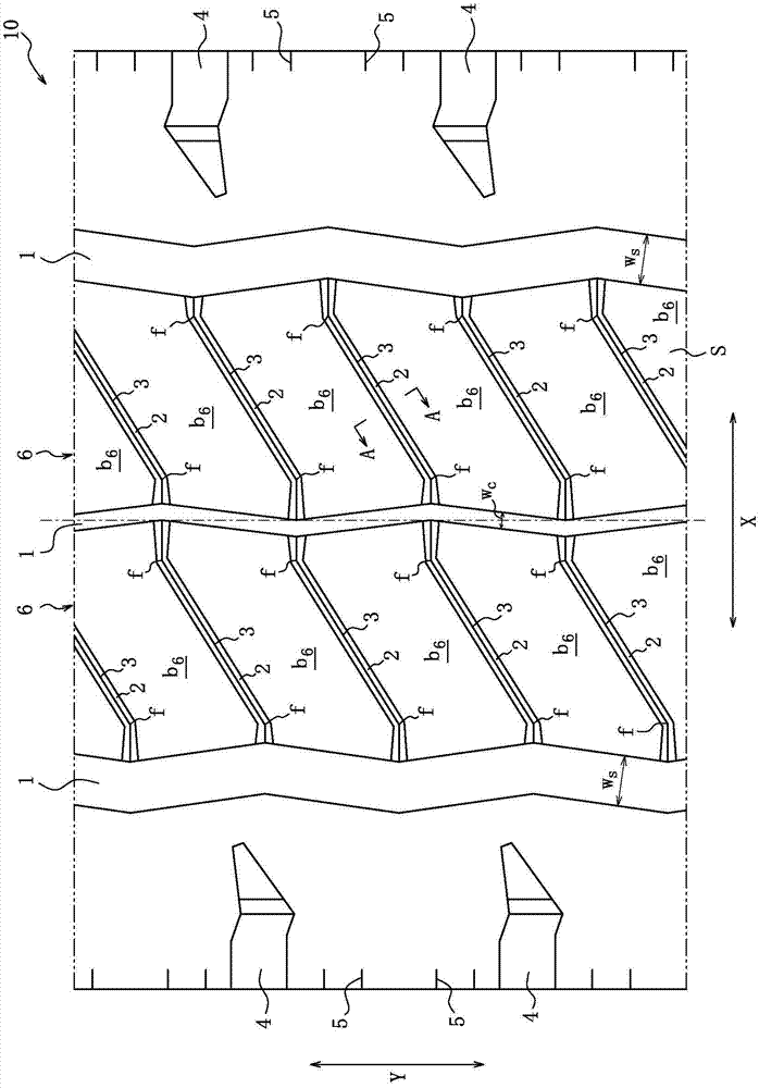
[0023] Below, while referring to the attached Figure 1 The tire of the present invention will be described in detail by taking an embodiment of the tire of the present invention as an example. figure 1 It is a partially developed view showing the tread contact surface S of the tire 10 according to the embodiment of the present invention. In addition, although illustration is omitted, this tire 10 includes: a carcass spanning between a pair of bead portions and composed of carcass layers of organic fiber cords or steel cords; the radially outer side of the tire, consisting of layers of steel cords; and the tread.

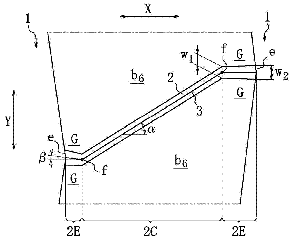
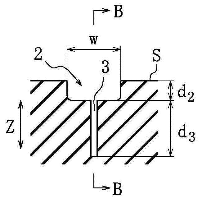
[0024] On the tread contact surface S of the tire 10, using the tire circumferential direction ( figure 1 A plurality of circumferential grooves 1 (three in the illustrated example) extending in the Y direction) divide two land portions 6, and a plurality of land portions 6 are arranged on the two land portions 6 respectively. The transverse grooves 2 extend obli...


PUM


Abstract

Provided is a tire which is configured so that driving stability and water discharge properties on a wet road surface can be maintained and so that the uneven wear of the treading surface of the tread can be minimized. A tire is configured in such a manner that the treading surface of the tread has lands defined by circumferential grooves extending in the circumferential direction of the tire, each of the lands having arranged therein lateral grooves extending across the land. The lateral grooves are arranged so that, when the lateral grooves are projected on the equatorial plane of the tire, lateral grooves adjacent to each other in the circumferential direction of the tire do not overlap each other. Each of the lateral grooves is composed of: a center region extending tilted relative to the width direction of the tread; and side regions extending from both ends of the center region toward circumferential grooves at a tilt angle relative to the width direction of the tread, the tilt angle being less than the tilt angle of the center region. Each of the side regions has a groove width expanding toward a circumferential groove. The lateral grooves have sipes extending inward in the radial direction of the tire from the bottoms of the lateral grooves, each of the sipes having a shallow bottom only in the center region, the shallow bottom being disposed near the boundary between at least the center region and a side region in such a manner that the start point of the shallow bottom is located at a distance from the boundary.

Description

technical field [0001] The present invention relates to a tire capable of suppressing uneven wear of a tread contact surface while maintaining steering stability and water drainage on a wet road. Background technique [0002] Conventionally, for the purpose of improving wet performance, a plurality of lateral grooves and sipes that traverse the land portion are provided in the land portion defined by the peripheral grooves of the tread contact surface. Patent Document 1 discloses a tire which is expected to further suppress the tire in the sipe on the basis of maintaining the improvement of the wet performance by using the shallow groove (transverse groove) and the sipe formed at the bottom of the groove. Uneven wear occurring around the front and back causes all the shallow grooves (transverse grooves) and sipes to incline in the same direction relative to the tire axial direction. [0003] patent documents [0004] Patent Document 1: Japanese Patent Laid-Open No. 2002-10...

Claims


Application Information

Patent Timeline
IPC IPC(8): B60C11/12B60C11/04
CPCB60C11/0306B60C11/125B60C11/1263B60C2011/0344B60C2011/0346B60C2011/0358B60C2011/0362B60C2011/0367B60C2011/1209B60C11/0327B60C2011/0334B60C2011/0353B60C2011/0365
Inventor 山本展之
Owner BRIDGESTONE CORP
Learn More