Buffer type conveyor line

A buffer conveyor line and buffer plate technology, applied in the direction of conveyor objects, transportation and packaging, can solve the problems affecting the quality of steel balls leaving the factory and the collision of collecting grooves, so as to achieve a wide range of use, reduce rolling speed, and save resources. Effect

Inactive Publication Date: 2015-01-14
WUXI MINGZHU STEEL BALL
View PDF10 Cites 12 Cited by
  • Summary
  • Abstract
  • Description
  • Claims
  • Application Information

AI Technical Summary

Problems solved by technology

[0002] The post-processing process of steel ball production includes multiple processes. After each process is completed, it needs to be transported to the next process or to the collection box through the conveyor line. The existing conveyor line is an inclined track, and the steel balls roll down on the track The speed is too fast, and when it slides into the collection box, due to the inertia problem, a serious collision occurs in the collection box, which affects the quality of the steel ball when it leaves the factory.

Method used


Image

  • Buffer type conveyor line
  • Buffer type conveyor line

Examples


Embodiment Construction

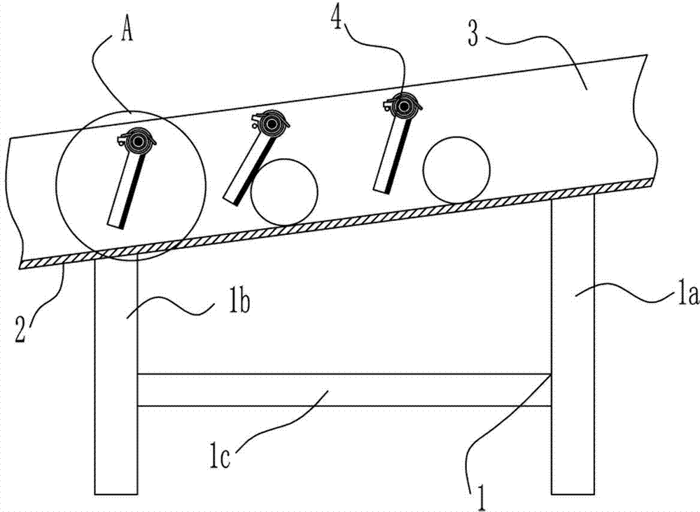
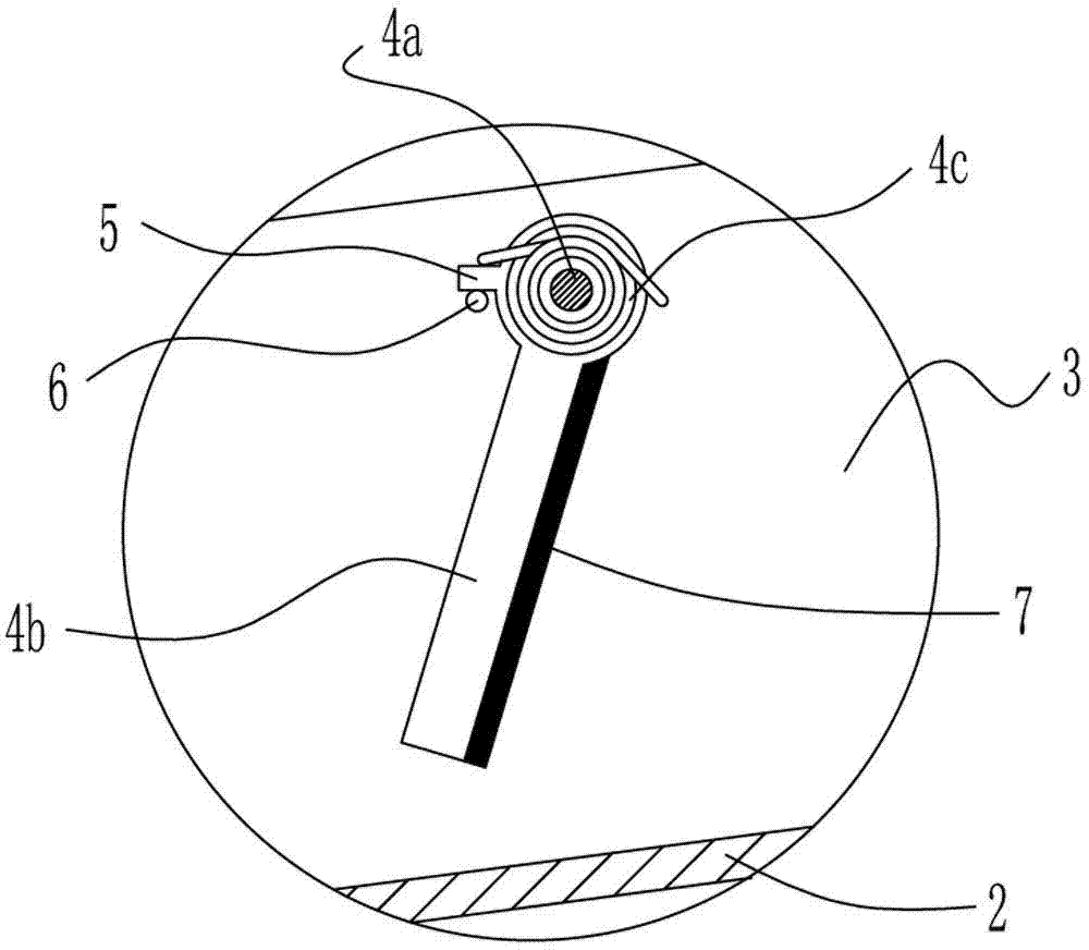
[0013] Such as figure 1 , figure 2 As shown, a buffer conveyor line according to the embodiment of the present invention mainly includes a bracket 1 and an inclined track located above the bracket 1. The inclined track includes a guide rail 2 and two identical baffles 3 fixed above the guide rail 2. Two baffles 3 are symmetrically fixed on both sides of the guide rail 2, and a plurality of identical buffer devices 4 are arranged between the two baffles 3, and the plurality of buffer devices 4 are located on the same straight line and evenly arranged along the inclination direction of the guide rail 2 Each buffer device 4 includes a rotating shaft 4a, a buffer plate 4b and a torsion spring 4c, the two ends of the rotating shaft 4a are respectively fixed on the two baffle plates 3, the buffer plate 4b is hinged with the rotating shaft 4a, and the torsion spring 4c is located between the buffer plate 4b and the rotating shaft 4a At the hinge, the buffer plate 4b is provided wit...


PUM


Abstract

The invention discloses a buffer type conveyor line which mainly comprises a support and an oblique track. The oblique track is positioned on the upper side of the support and comprises a guide rail and two identical barriers, the barriers are fixed to the upper side of the guide rail, a plurality of identical buffer devices are arranged between the two barriers, are positioned on the same straight line and are uniformly arranged along the oblique direction of the guide rail, each buffer device comprises a rotary shaft, a buffer plate and a torsional spring, two ends of each rotary shaft are respectively fixed onto the two barriers, each buffer plate is hinged to the corresponding rotary shaft, each torsional spring is positioned at a hinged joint of the corresponding buffer plate and the corresponding rotary shaft, and limiting stoppers are arranged on the buffer plates, cling onto the barriers and are matched with fixing pins on the barriers. The buffer type conveyor line has the advantages that rolling speeds of steel balls can be effectively reduced, accordingly, collision damage to the steel balls due to the fact that the steel balls enter collecting grooves at excessively high speeds can be prevented, the quality of the steel balls can be guaranteed when the steel balls are delivered from factories, loss can be reduced for enterprises, resources can be saved, and the buffer type conveyor line is wide in service range.

Description

technical field [0001] The invention relates to the field of production and processing of steel balls, in particular to a buffer conveying line. Background technique [0002] The post-processing process of steel ball production includes multiple processes. After each process is completed, it needs to be transported to the next process or to the collection box through the conveyor line. The existing conveyor line is an inclined track, and the steel balls roll down on the track The speed is too fast, and when it slides into the collection box, due to the inertia problem, a serious collision occurs in the collection box, which affects the factory quality of the steel ball. Contents of the invention [0003] In order to solve the above-mentioned technical problems, the present invention provides a buffer conveyor line. The track of the conveyor line is equipped with multi-stage deceleration and buffer devices to prevent steel balls from sliding and being damaged due to excessi...

Claims


Application Information

Patent Timeline
Patent Type & Authority Applications(China)
IPC IPC(8): B65G47/88
Inventor 吴昊
Owner WUXI MINGZHU STEEL BALL
Why Eureka
Try Eureka