Smart recovery system
a recovery system and intelligent technology, applied in the field of recovery systems, can solve the problems of inability to assess the situation, and inability to deploy the correct device or system, so as to reduce the forward speed or the aircraft, and reduce the downward speed of the aircra
- Summary
- Abstract
- Description
- Claims
- Application Information
AI Technical Summary
Benefits of technology
Problems solved by technology
Method used
Image
Examples
example 1
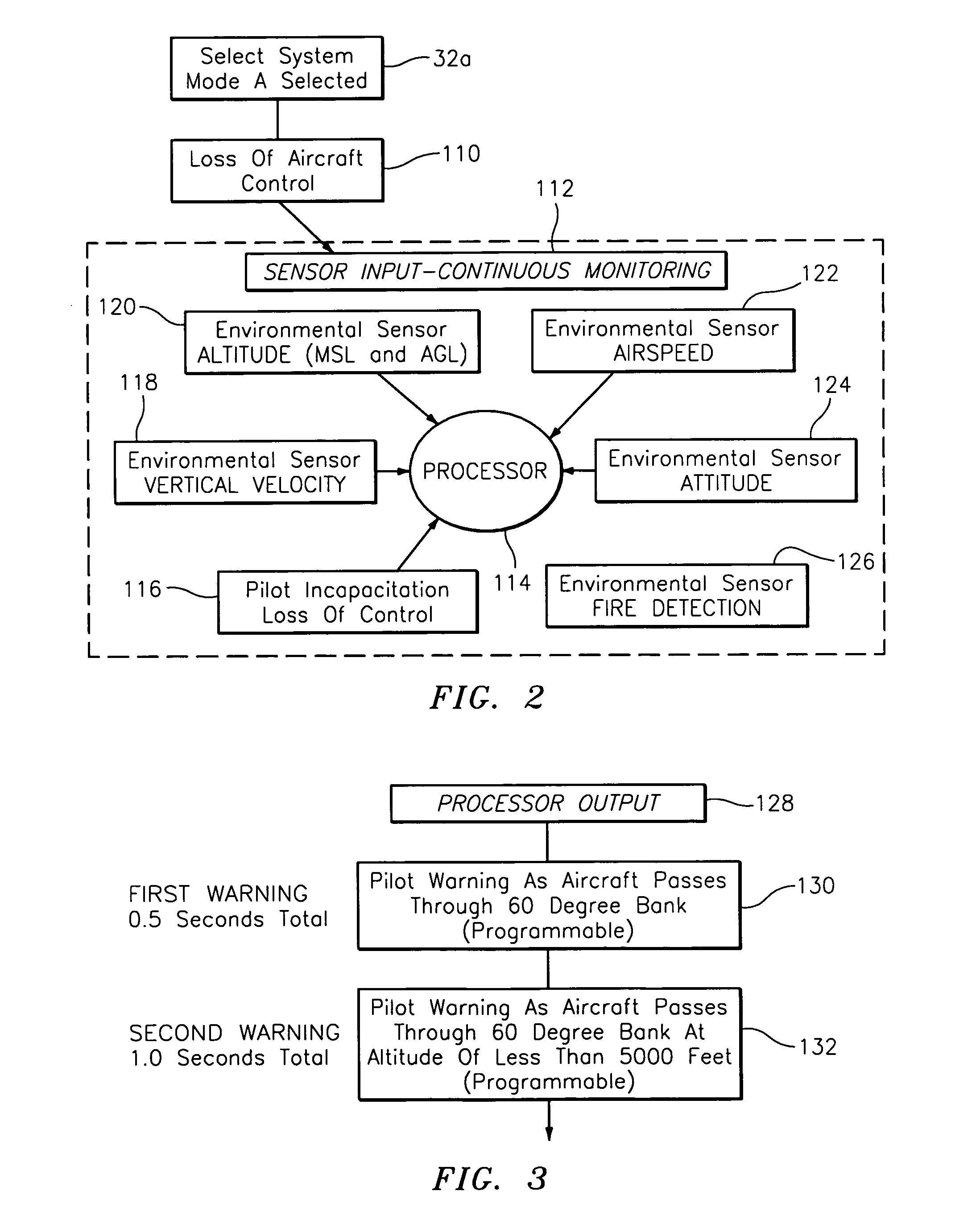
[0072]One example of the present invention, as shown in FIGS. 2-5, a pilot of a Cessna 210 (a 6 seat, high-performance, retractable-gear single-engine general, military and commercial aviation aircraft) in a night flight at 2,500 feet above ground level over unpopulated terrain experiences disorientation due to loss of horizon reference, which causes the aircraft to roll left past 90 degrees. In this example, the smart recovery system of the present invention is in automatic mode 32a. In particular, an event, such as the loss of aircraft control is observed at step 110 by sensors at step 112 which continuously monitor the aircraft. In order to continuously monitor the aircraft, the smart recovery system includes at least one loss of control sensor 116, vertical velocity sensor 118, altitude sensor 120, airspeed sensor 122, attitude sensor 124, and fire detection sensor 126. The data received by loss of control sensor 116, vertical velocity sensor 118, altitude sensor 120, airspeed s...
example 2
[0081]In an alternate embodiment of the present invention, shown in FIGS. 6-8, in which fire is detected in a Cessna 172 (a four-seat, single-engine, high-wing fixed-wing aircraft) or a Beechcraft King Air (a twin-turboprop aircraft) in flight at about 6,500 feet mean sea level and about 4,500 feet above ground level. The smart recovery system is in automatic mode 32a. In an event, such as engine fire is observed at step 210 by the smart recovery system, as shown in FIG. 6. In order to continuously monitor the aircraft in step 212, the smart recovery system includes at least one loss of control sensor 216, vertical velocity sensor 218, altitude sensor 220, airspeed sensor 222, attitude sensor 224, and fire detection sensor 226. The data received by loss of control sensor 216, vertical velocity sensor 218, altitude sensor 220, airspeed sensor 222, attitude sensor 224, and fire detection sensor 226 is processed and stored in processor 214.
[0082]The data which is processed and stored i...
example 3
[0085]In another embodiment of the present invention in operation is shown in FIGS. 9-10, the pilot of a Beechcraft King Air (a twin-turboprop aircraft), after activating the fire extinguisher system to put out a fire in the engine, shuts down the engine, which slows the aircraft below single engine stall speed causing the aircraft to roll to the right in a tight spin. The aircraft is on two mile final at about 1000 feet above ground level. In order to continuously monitor the aircraft in step 312, the smart recovery system includes at least one loss of control sensor 316, vertical velocity sensor 318, altitude sensor 320, airspeed sensor 322, attitude sensor 324, and fire detection sensor 326. The data received by loss of control sensor 316, vertical velocity sensor 318, altitude sensor 320, airspeed sensor 322, attitude sensor 324, and fire detection sensor 326 is processed and stored in processor 314.
[0086]The data which is processed and stored in processor 314 is output at step ...
PUM
 Abstract
Description
Claims
Application Information
 - R&D
- Intellectual Property
- Life Sciences
- Materials
- Tech Scout
- Unparalleled Data Quality
- Higher Quality Content
- 60% Fewer Hallucinations
Browse by: Latest US Patents, China's latest patents, Technical Efficacy Thesaurus, Application Domain, Technology Topic, Popular Technical Reports.
© 2025 PatSnap. All rights reserved.Legal|Privacy policy|Modern Slavery Act Transparency Statement|Sitemap|About US| Contact US: help@patsnap.com


