Eureka AIR delivers breakthrough ideas for toughest innovation challenges, trusted by R&D personnel around the world.

Production line fast feeding mechanism and working method with intelligent deceleration device

A feeding mechanism and production line technology, applied in the direction of shock absorbers, shock absorbers, mechanical equipment, etc., can solve problems such as inability to decelerate, material flying out, etc., achieve the effects of prolonging life, relieving intracavity pressure, and being applicable to a wide range of places

Active Publication Date: 2016-02-03
CHANGZHOU INST OF LIGHT IND TECH
View PDF6 Cites 2 Cited by
  • Summary
  • Abstract
  • Description
  • Claims
  • Application Information

AI Technical Summary

Problems solved by technology

[0004] The technical problem to be solved by the present invention is to provide a fast feeding mechanism and working method of the production line with an intelligent deceleration device. The feeding mechanism and working method solve the problem that when the material delivered by the pallet reaches the target area, it cannot be decelerated, causing the material to fly out. problem, so that the material can be delivered to the target position accurately, and the material can be effectively prevented from flying out

Method used


Image

  • Production line fast feeding mechanism and working method with intelligent deceleration device
  • Production line fast feeding mechanism and working method with intelligent deceleration device
  • Production line fast feeding mechanism and working method with intelligent deceleration device

Examples


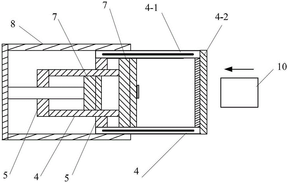
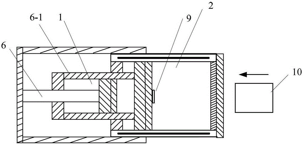
Embodiment 1

[0026] See figure 1 , one A production line feeding mechanism, comprising: a guide rail body 11, a slide block 10 that is slidably fitted on the guide rail body 11, and a material tray 1-2 is provided on the slide block 10; A speed reduction device 1-1 for deceleration.

[0027] The reduction gear 1-1 is a buffer.

[0028] See figure 2 , image 3 and Figure 6, the buffer is a two-stage buffer, and the two-stage buffer includes: a first-stage buffer 1 and a final-stage buffer 2; the first-stage buffer 1 and the final-stage buffer 2 respectively include: cylindrical, And be used for filling the cylinder body 4 of cushioning medium, be provided with cylinder head 5 in the open end seal of this cylinder body 4, in the central through hole of described cylinder head 5, seal movable fit a piston rod 6, the right end of this piston rod 6 There is a piston body assembly 7 for adjusting the back-and-forth flow of the medium, the piston body assembly 7 is suitable for piston mo...

Embodiment 2

[0039] See figure 1 , figure 2 , image 3 and Figure 6 , a working method of a production line feeding mechanism based on the embodiments;

[0040] The feeding mechanism of the production line includes: a guide rail body 11, a slide block 10 slidingly fitted on the guide rail body 11, and a material tray 1-2 is arranged on the slide block 10; 10. A deceleration device 1-1 for decelerating.

[0041] The reduction gear 1-1 is a buffer, and the buffer is a two-stage buffer.

[0042] The two-stage buffer includes: a first-stage buffer 1 and a final-stage buffer 2; the first-stage buffer 1 and the last-stage buffer 2 respectively include: a cylinder 4 that is cylindrical and is used to fill a buffer medium A cylinder cover 5 is sealed at the open end of the cylinder body 4, and a piston rod 6 is fitted in the central through hole of the cylinder cover 5 for sealing and movable movement. The right end of the piston rod 6 is provided with a piston body for adjusting the back a...


PUM


Abstract

The invention relates to a production line rapid-feeding mechanism with an intelligent speed-decreasing device and a working method. The production line rapid-feeding mechanism comprises a guide rail body and a sliding block matched with the guide rail body in a sliding mode, and a material tray is arranged on the sliding block; the speed-decreasing device is arranged at one end of the guide rail body and used for decreasing the speed of the sliding block, wherein the speed-decreasing device is a two-stage buffering device. A processor and a current driving module are used for generating a magnetic field matched with impact pressure to attract the sliding block, and it is prevented that because the impact energy is excessively large, the sliding block makes materials fly off due to inertia.

Description

technical field [0001] The invention relates to a fast feeding mechanism and a working method of a production line, in particular to a feeding mechanism and a working method of an intelligent speed reduction device. Background technique [0002] In the field of cushioning and shock absorption, the reduction device is widely used, and its main function is to absorb various impact energy, protect equipment and reduce noise. [0003] During the working process of the feeding mechanism, the pallet is often made to move back and forth, but when the slider located under the pallet sends the material to the target position, if it does not slow down, the material will fly out due to inertia. How to make the material reach the target position , it is a technical problem in this field to effectively reduce the moving speed of the tray and make the material reach the target position smoothly. Contents of the invention [0004] The technical problem to be solved by the present invent...

Claims


Application Information

Patent Timeline
Patent Type & Authority Patents(China)
IPC IPC(8): F16F9/26F16F9/34
CPCF16F9/26F16F9/512F16F9/52
Inventor 谈雪梅
Owner CHANGZHOU INST OF LIGHT IND TECH
Why Eureka
Eureka Blog
Learn More