Device for testing stress-strain of plastic concrete/mortar and use method of device

A plastic concrete, stress-strain technology, applied in the field of civil engineering, to achieve the effect of improving test accuracy and ensuring changes

Active Publication Date: 2015-01-14
TONGJI UNIV
View PDF9 Cites 11 Cited by
  • Summary
  • Abstract
  • Description
  • Claims
  • Application Information

AI Technical Summary

Problems solved by technology

However, there are very few studies on early concrete / mortar stress-strain testing, and there are few reports on related testing devices

Method used


Image

  • Device for testing stress-strain of plastic concrete/mortar and use method of device
  • Device for testing stress-strain of plastic concrete/mortar and use method of device
  • Device for testing stress-strain of plastic concrete/mortar and use method of device

Examples


Embodiment

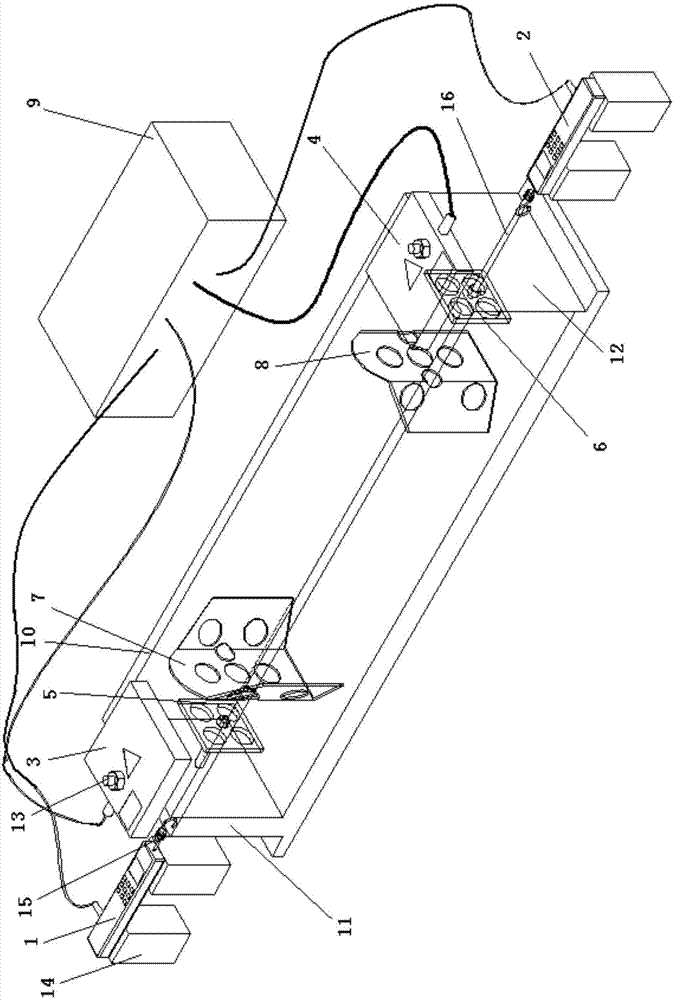
[0043] Such as figure 1 As shown, a device for testing the stress-strain of plastic concrete / mortar, the device includes a dynamometer a1, a dynamometer b2, a laser displacement sensor c3, a laser displacement sensor d4, a force transmission unit, a laser target unit, and a data collector 9 and the mold 10, the left and right sides of the mold 10 are respectively equipped with a dynamometer a1 and a dynamometer b2, the laser target unit and the force transmission unit are all arranged in the inner cavity of the mold 10, and the left and right ends of the top of the mold 10 are respectively equipped with The laser displacement sensor c3 and the laser displacement sensor d4, and the data collector 9 are respectively connected to the dynamometer a1, the dynamometer b2, the laser displacement sensor c3 and the laser displacement sensor d4 through circuits.

[0044] The laser target unit includes a laser target e7 and a laser target f8 , wherein the laser target e7 and the laser ta...


PUM


Abstract

The invention relates to a device for testing stress-strain of plastic concrete/mortar. The device comprises a forcemeter a, a forcemeter b, a laser displacement sensor c, a laser displacement sensor d, a force transmission unit, a laser target unit, a data acquirer and a die, wherein the forcemeter a and the forcemeter b are respectively arranged on the left side and the right side of the die; the laser target unit and the force transmission unit are arranged in an inner cavity of the die; the laser displacement sensor c and the laser displacement sensor d are respectively arranged at the left end and the right end of the top of the die; the data acquirer is connected with the laser displacement sensor c and the laser displacement sensor d respectively through circuits. Compared with the prior art, the device disclosed by the invention is simple in structure, convenient to operate and high in test precision, can automatically and continuously test the stress and the strain in the concrete/mortar in any stage from the moment of pouring, and the practicability is high.

Description

technical field [0001] The invention belongs to the technical field of civil engineering, and relates to a device for testing the stress and strain of plastic concrete or mortar and a use method thereof. Background technique [0002] Shrinkage and expansion of plastic concrete or mortar are the main causes of cracking. The cracks of concrete / mortar are related to the constrained conditions of its deformation: the unrestrained free shrinkage makes the particles inside the concrete / mortar close to each other, which has no adverse effect on the performance of the concrete / mortar and will not produce cracks. Unconstrained free expansion will not cause cracking, but the internal particle distance of concrete / mortar increases, making the structure loose, which is not good for the strength of concrete / mortar. [0003] In practical situations, the shrinkage and expansion of concrete / mortar are subject to different degrees of external and internal constraints. Under external constr...

Claims


Application Information

Patent Timeline
Patent Type & Authority Applications(China)
IPC IPC(8): G01N3/00G01N3/06G01L5/00G01B11/16
Inventor 刘斯凤王培铭万婷婷
Owner TONGJI UNIV
Why Eureka
Try Eureka