Fastener with whistle

A whistle and buckle technology, applied to belt buckles, fasteners, whistle and other directions, can solve the problems of inconvenient use, small range of whistle, and random rotation of whistle, etc., to achieve the effect of expanding the range of activities

Inactive Publication Date: 2015-01-21
SHANGHAI BROS SPORTS ACCESSORIES
View PDF8 Cites 7 Cited by
  • Summary
  • Abstract
  • Description
  • Claims
  • Application Information

AI Technical Summary

Problems solved by technology

[0004] Taking U.S. Patent Publication No. 6,668,428 as an example, the problem existing in the combination structure of whistle and buckle adopted in the prior art is: in a dangerous emergency state, the whistle with integral structure of the buckle needs to untie the buckle to It is extremely inconvenient to use for users who are in danger
[0006] However, it is a prerequisite for the installation of the whistle that the hasp body has a reliable sliding part. In an emergency, if the user is in a state of panic, if he wants to take off the whistle connected to the hasp body and use it, can he complete a series of whistles? The precise disassembly action is debatable. This is determined by the connection structure between the whistle and the buckle body, and the whistle cannot complete the rotation or swing action on the buckle body. The range of movement of the whistle is too small to still affect the whistle. Effect
[0007] In the case that the whistle is installed on the buckle body, such as the Chinese invention patent whose publication number is CN101721017B, it is impossible to arbitrarily turn the direction of the whistle head according to the user's habits

Method used


Image

  • Fastener with whistle
  • Fastener with whistle
  • Fastener with whistle

Examples


Embodiment Construction

[0064] In order to make the technical means, creative features, goals and effects achieved by the present invention easy to understand, the present invention will be further described below in conjunction with specific illustrations.

[0065] Hereinafter, the same reference numerals represent the same structure, such as reference numeral 10, which represents the buckle, and wherein the buckle includes but not limited to the following situations: buckle, square buckle, day-shaped buckle, trapezoidal buckle, hook buckle, tent hook, D-shaped buckle.

[0066] Hereinafter, a buckle is used as a representative of the buckle for a detailed description.

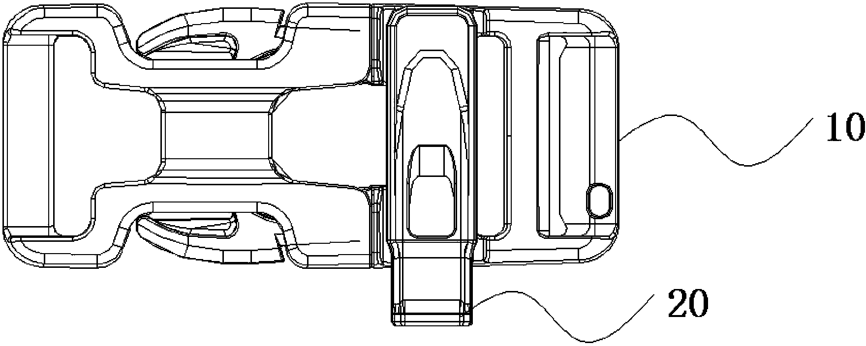
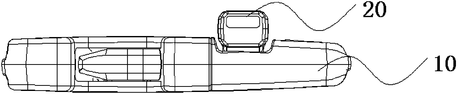
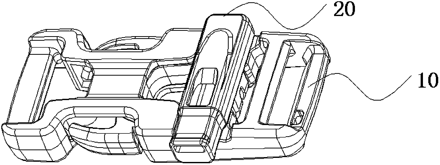
[0067] see Figure 1-30 , a buckle with a whistle, which includes a buckle 10 (such as a buckle including a female buckle 10b and a male buckle 10a) and a whistle 20 detachably connected to the buckle, the whistle is used as an emergency, and the buckle has A cylindrical carrier 100, and the cylindrical carrier is arranged on the m...


PUM


Abstract

The invention discloses a fastener with a whistle. The fastener comprises a fastener body, the whistle and a clamping mechanism. The fastener body is provided with a cylindrical supporting body. The edge of the cylindrical supporting body is provided with at least one rotating space. The axial end of the cylindrical supporting body is provided with whistle carrying surfaces. The whistle comprises a whistle body. A blowing nozzle of the whistle body comprises an extension part and protruding steps, wherein the protruding steps are arranged at the front end and the rear end of the extension part. The clamping mechanism is arranged on the whistle body and provided with an inner groove, wherein the groove wall of the inner groove is of a parabolic shape; the length of the clamping mechanism is smaller than or equal to the length of the cylindrical supporting body. The side face, provided with the clamping mechanism, of the whistle body is provided with a front-end plane and a rear-end plane which are matched with the whistle carrying surfaces. The cylindrical supporting body of the fastener is matched with the inner groove structure of the whistle so that quick insertion connection of the whistle can be achieved; moreover, the groove wall of the inner groove has deformability, so the whistle can be quickly taken out in the radial direction of the cylindrical supporting body on an emergency condition without limitation of one direction while the clamping degree of the groove wall of the inner groove can make the whistle reliably mounted onto the fastener.

Description

technical field [0001] The invention relates to a buckle with a whistle. Background technique [0002] Fasteners such as buckles are ideal accessories for items such as backpacks and are installed. [0003] In the process of carrying out outdoor sports, the use of buckles is essential. As outdoor sports are high-risk sports, timely detection of accidents or the attention of nearby people is the prerequisite for assistance. In view of this, combining the whistle with the buckle is a technical solution proposed in US Patent Publication No. 6,668,428. [0004] Taking U.S. Patent Publication No. 6,668,428 as an example, the problem existing in the combination structure of whistle and buckle adopted in the prior art is: in a dangerous emergency state, the whistle with integral structure of the buckle needs to untie the buckle to It is extremely inconvenient to use for users who are in a dangerous state. Moreover, exposure of the whistle to contamination is an unavoidable hygi...

Claims


Application Information

Patent Timeline
Patent Type & Authority Applications(China)
IPC IPC(8): A44B11/00A44B11/26G10K5/00
Inventor 王满堂
Owner SHANGHAI BROS SPORTS ACCESSORIES
Why Eureka
Try Eureka