
An illuminated surgical dilator

A dilator and surgery technology, applied in the direction of surgery, medical science, etc., can solve the problems of affecting the operation and poor effect, and achieve the effect of good lighting effect, eliminating shadows, and not occupying the operation space.

Inactive Publication Date: 2016-11-23
王刚
View PDF6 Cites 0 Cited by
  • Summary
  • Abstract
  • Description
  • Claims
  • Application Information

AI Technical Summary

Problems solved by technology

This invention causes shadows to be generated inside the surgical opening during the operation, which affects the operation, and the effect is very poor

Method used


Image

  • An illuminated surgical dilator
  • An illuminated surgical dilator
  • An illuminated surgical dilator

Examples


Embodiment Construction

[0023] The present invention will be further described below with reference to the accompanying drawings.

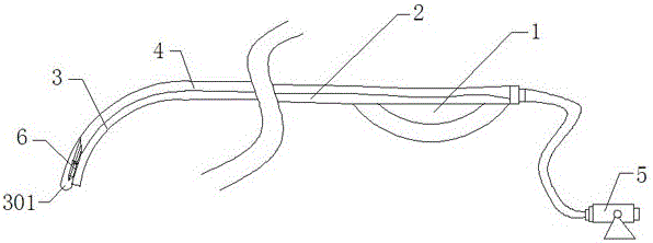
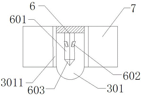
[0024] Such as figure 1 As shown, this embodiment includes a handle 1 and a hook body 2 . The grip of the palm of the handle 1 is concave, which can prevent the palm from slipping off, and the lower part is provided with a bracelet to ensure the firmness of the grip. The front end of the hook body 2 is bent downward to form a hook portion 3, and a light-transmitting portion 301 is arranged on the hook portion 3. Both the inside of the hook body 2 and the handle 1 are hollowed with a light-guiding optical fiber 4 with a diameter of 3 mm. One end is connected with the light guide fiber 4, and the other end of the light guide fiber 4 is connected with an external light source 5, and the external light source uses a 7Wled white light spotlight, and the emission angle of the spotlight is below 30°.

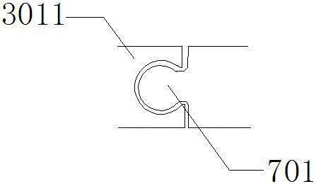
[0025] Such as Figure 1 to Figure 2 As shown, the light transmitting par...


PUM


Abstract

The invention provides an illuminable surgical dilator which comprises a handle and a hook body, wherein the front end of the hook body is bent downwards to form a hook part; a light transmission part is arranged on the hook part; a light guide optical fiber hollowly runs through both the hook body and the handle and is connected with the rear end of the light transmission part; an external light source is connected to the other end of the light guide optical fiber; a prism mechanism capable of dispersing one-way light to form 360-degree light is arranged in the light transmission part. Due to the design, the illuminable surgical dilator has the advantages that the one-way light is dispersed to form the 360-degree light and the effective illumination area is enlarged; the illuminable surgical dilator can be used for removing a shadow generated during illuminating while providing illumination for surgical opening.

Description

technical field [0001] The invention relates to surgical instruments, in particular to an illuminable surgical dilator. Background technique [0002] In modern medical operations, the surgical opening needs to be expanded. However, the surgical opening is generally small, which makes the lighting effect of the shadowless lamp very small. At present, a small illuminator is usually used to extend into the surgical opening for illumination, but this method There is too much occupation of the small surgical area, which slows down the operation speed and makes the operation process cumbersome. [0003] Another example is the invention patent, No. CN 102335018 A, which discloses a surgical retractor with a retractor body, a vertical rod formed at the front end of the retractor body, and a cold light source wick is arranged on the vertical rod at the front end of the retractor body. This invention causes shadows to be generated inside the operation opening during the operation, wh...

Claims


Application Information

Patent Timeline
Patent Type & Authority Patents(China)
IPC IPC(8): A61B17/02
CPCA61B17/0218
Inventor 王刚申屠刚李强徐云钦
Owner 王刚
Learn More