A permanent magnet coupling control method and a permanent magnet governor

A technology of permanent magnetic coupling and governor, applied in the direction of electromechanical transmission, electromechanical devices, electrical components, etc., can solve the current situation that the hard connection between the motor and the load cannot be changed, the impact of the life of the transmission system cannot be removed, and the adaptation to changes in the surrounding environment Poor capacity and other problems, to achieve the effect of low maintenance cost, long service life, and eliminate the impact

Inactive Publication Date: 2018-11-13
SHENYANG POLYTECHNIC UNIV
View PDF3 Cites 0 Cited by
  • Summary
  • Abstract
  • Description
  • Claims
  • Application Information

AI Technical Summary

Problems solved by technology

[0005] 2. Power electronic devices are high-precision components, poor adaptability to changes in the surrounding environment, sensitive to external factors, easy to damage, and limited service life
[0007] 4. The frequency converter is assembled between the motor and the power supply, which cannot change the status quo of the hard connection between the motor and the load, and cannot remove the influence of the vibration of the motor and load on the life of the transmission system
These permanent magnet coupling speed governors regulate the torque and speed by adjusting the axial position of the conductor rotor and the permanent magnet rotor, that is, adjusting the action area between the conductor rotor and the permanent magnet rotor. Many problems, reducing the practicality

Method used


Image

  • A permanent magnet coupling control method and a permanent magnet governor
  • A permanent magnet coupling control method and a permanent magnet governor
  • A permanent magnet coupling control method and a permanent magnet governor

Examples


Embodiment Construction

[0043] The present invention will be described in more detail below in conjunction with the description figures and embodiments.

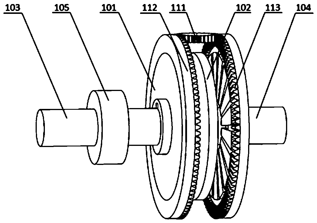
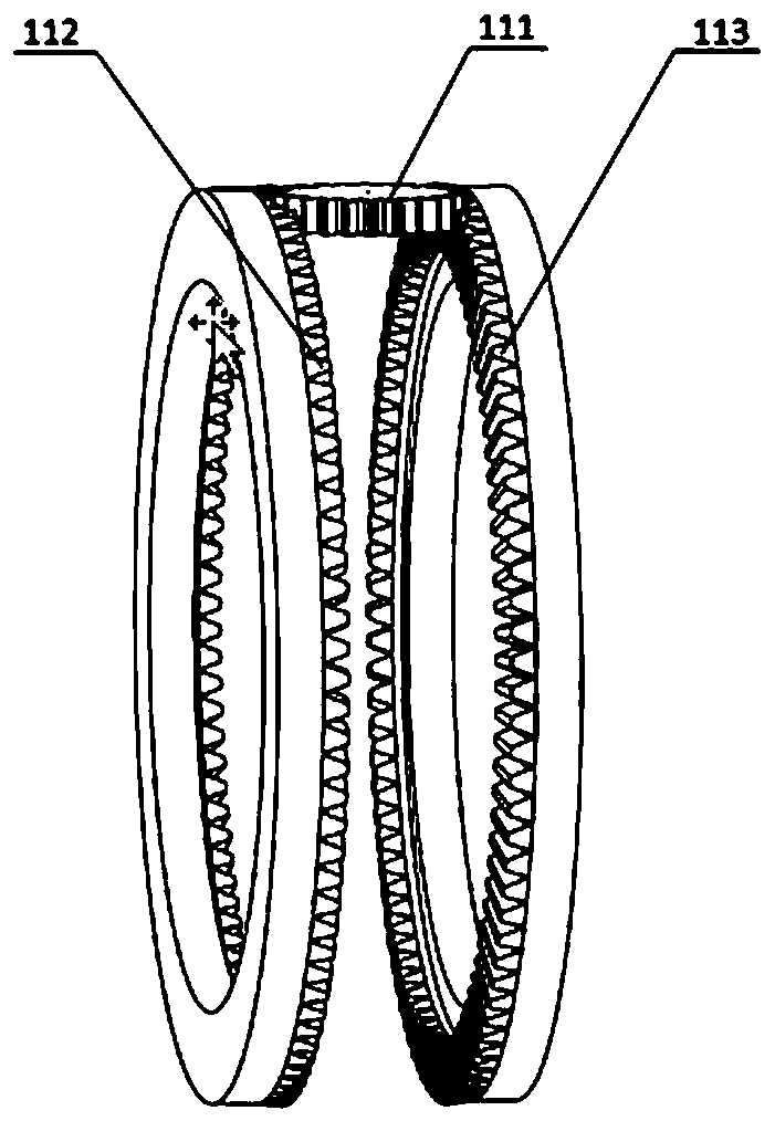
[0044] Such as Picture 1-1As shown, an embodiment of the present invention, a disc-shaped permanent magnet coupling speed governor is composed of a permanent magnet rotor 101 and a conductor rotor that is a conductor disc 102. The external connection end of the conductor disc 102 is connected to the motor shaft 104 connection, the external connection end of the permanent magnet rotor 101 is connected to the load shaft 103, the controller 105 of the manipulation mechanism is assembled between the permanent magnet rotor 101 and the load shaft 103, and the manipulation mechanism controller 105 is used for Adjust the central control gear 112, gear 113 and gear 114, adjust the relative circumferential position angle of the permanent magnet poles on both sides of the permanent magnet rotor 101, change the coupling strength of the conductor disk 102 cutti...


PUM


Abstract

A permanent magnet coupling control method and a permanent magnet governor, the method includes a permanent magnet coupling governor, the permanent magnet governor is composed of a conductor rotor, a permanent magnet rotor and an operating mechanism, the permanent magnet coupling governor The conductor rotor is a conductor disc or a conductor ring. The permanent magnet rotor in the permanent magnet coupling governor includes two iron disc supports or iron ring supports symmetrically placed on both sides of the conductor rotor, and the iron disc support or iron ring support is close to the conductor rotor side. The permanent magnets are placed at intervals according to the alternating polarity, and the permanent magnets maintain a coupling state without contact with the conductor disc or the conductor ring. By changing the relative position of the two iron disc brackets or iron ring brackets along the circumferential direction, the conductor on both sides of the rotor can be changed. The relative circumferential position angle of the permanent magnet poles on the iron plate support or iron ring support is used to regulate the coupling strength of the conductor cutting magnetic field, change the induced eddy current in the conductor plate or conductor ring, and thereby change the conductor rotor conductor plate or conductor ring. The torque generated by the coupling strength magnetic field can realize the transmission speed regulation.

Description

technical field [0001] The invention relates to a frequency converter, in particular to a permanent magnet coupling control method and a permanent magnet governor, belonging to the technical field of consumption reduction and energy saving. Background technique [0002] At present, frequency converters are widely used in the field of motor speed regulation. The control method is to change the input voltage frequency of the motor to control the speed of the motor and load. With the help of the high-efficiency and controllable advantages of power electronic devices, the AC power supply is adjusted by rectification, filtering, and inversion, and then changed into a voltage whose amplitude and frequency meet the requirements of the motor's working conditions, so as to optimize the operating efficiency of the motor and achieve energy saving and emission reduction etc. purpose. [0003] However, there are the following disadvantages in using the frequency converter to adjust the...

Claims


Application Information

Patent Timeline
Patent Type & Authority Patents(China)
IPC IPC(8): H02K51/00
CPCH02K51/00
Inventor 安跃军高丹安辉孙丹薛丽萍
Owner SHENYANG POLYTECHNIC UNIV
Why Eureka
Try Eureka