Electric punching machine

An electric punch and punch technology, applied in metal processing and other directions, can solve the problems of inconvenience, single electric operation, and low punching force.

Inactive Publication Date: 2015-01-21
北京曼特尔进出口贸易有限公司
View PDF5 Cites 3 Cited by
  • Summary
  • Abstract
  • Description
  • Claims
  • Application Information

AI Technical Summary

Problems solved by technology

[0003] Existing electric punch press generally comprises motor, is connected with running wheel on the motor, and described running wheel and flywheel are driven by belt, and described flywheel is connected with crankshaft, and described crankshaft is provided with punch, and described punch is provided with upper Die, when this kind of electric punching machine is punching, the flywheel is driven by the motor to rotate, so that the crankshaft drives the punch to move up and down to realize punching. In the field of punching holes in plastic sheets, the punching force is not large, so manual operation can be used. Existing electric punching machines generally only have a single electric operation, and it is not convenient to use a motor to drive the punching machine in case of a power failure or when punching a sample.

Method used


Image

  • Electric punching machine
  • Electric punching machine

Examples


Embodiment Construction

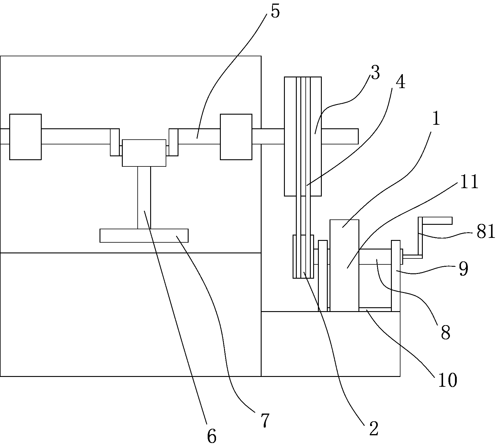
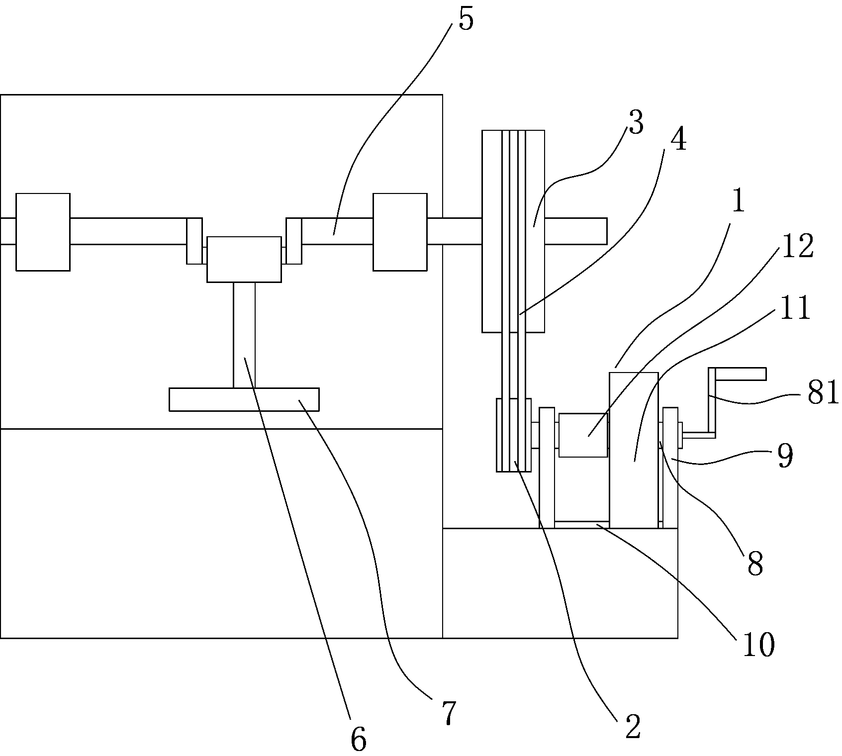
[0010] The present invention will be described in further detail below in conjunction with accompanying drawing and specific embodiment: see Figure 1 to Figure 2 , an electric punching machine, comprising a motor 1, a rotating wheel 2 is connected to the motor 1, the rotating wheel 2 and a flywheel 3 are driven by a belt 4, the flywheel 3 is connected to a crankshaft 5, and a punch is arranged on the crankshaft 5 6. The punch 6 is provided with an upper die 7, the motor 1 includes a stator 11 and a rotor 12, the rotor 12 is fixed on the rotating shaft 8, and the rotating shaft 8 is rotatably connected to the bracket 9, and the stator 11 The bottom is provided with a slide rail 10, the slide rail 10 is parallel to the rotating shaft 8, and the end of the rotating shaft 8 is provided with a rocker 81. In this embodiment, there are two brackets 9 and they are arranged on the rotor 12 On both sides, the distance between the two supports 9 is greater than twice the width of the st...


PUM


Abstract

The invention discloses an electric punching machine comprising a motor. A rotating wheel is connected to the motor. The rotating wheel is in transmission with a flywheel through a belt. The flywheel is connected with a bent axle. A punch is arranged on the bent axle. An upper die is arranged on the punch. The motor comprises a stator and a rotor. The rotor is fixed on a rotating shaft. The rotating shaft is rotationally connected to a support frame. A sliding rail is arranged at the bottom of the stator. The sliding rail is parallel to the rotating shaft. A rocking handle is arranged at the end of the rotating shaft. During normal working of the punching machine, the rotor is electrified to rotate to drive the rotating shaft to rotate, the rotating shaft drives the rotating wheel to rotate, the rotating wheel drives the flywheel to rotate, and the flywheel drives the bent axle to rotate to realize punching. During power failure, the rotating shaft bears large electromagnetic resistance due to direct rotation, so that the stator is slid towards the other side of the sliding rail to a position where the rotor is slid out, and then, the rocking handle is rotated to realize punching.

Description

technical field [0001] The invention relates to an electric punching machine for punching holes, in particular to a punching machine which can be punched manually when the power is cut off. Background technique [0002] Punch production is mainly for sheet metal. Through the mold, blanking, punching, forming, deep drawing, trimming, fine blanking, shaping, riveting and extrusion parts can be made, which are widely used in various fields. [0003] Existing electric punch press generally comprises motor, is connected with running wheel on the motor, and described running wheel and flywheel are driven by belt, and described flywheel is connected with crankshaft, and described crankshaft is provided with punch, and described punch is provided with upper Die, when this kind of electric punching machine is punching, the flywheel is driven by the motor to rotate, so that the crankshaft drives the punch to move up and down to realize punching. In the field of punching holes in plas...

Claims


Application Information

Patent Timeline
Patent Type & Authority Applications(China)
IPC IPC(8): B26F1/02B26D5/08B26D5/10
CPCB26D5/086B26D5/10B26D5/14B26F1/02
Inventor 褚岳辉
Owner 北京曼特尔进出口贸易有限公司
Why Eureka
Try Eureka