Lens for lighting device and lighting device with same

A lighting device and lens technology, which can be applied to the cooling/heating device of the lighting device, the components of the lighting device, the lighting device, etc., can solve the problems of restricting the application environment of such products and increasing the cost.

Inactive Publication Date: 2015-01-21
OSRAM GMBH
View PDF1 Cites 4 Cited by
  • Summary
  • Abstract
  • Description
  • Claims
  • Application Information

AI Technical Summary

Problems solved by technology

However, these inventions all need to use multiple LED chips as the basis for realizing multidirectional or omnidirectio

Method used


Image

  • Lens for lighting device and lighting device with same
  • Lens for lighting device and lighting device with same
  • Lens for lighting device and lighting device with same

Examples


Embodiment Construction

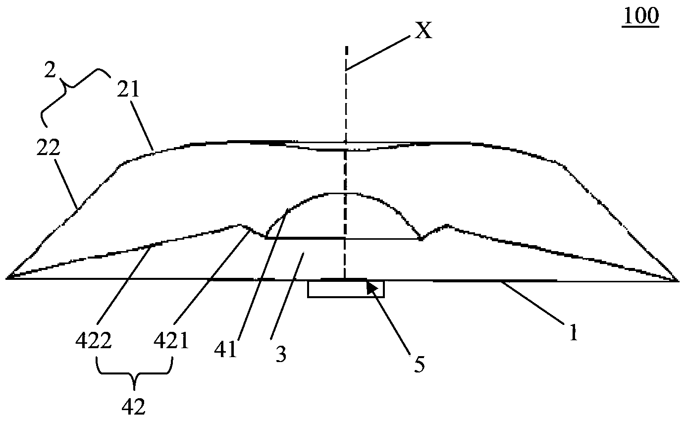
[0029] figure 1 is a schematic cross-sectional view of a lens 100 according to an embodiment of the present invention, such as figure 1 As shown, the lens 100 can be designed to be rotationally symmetrical about the optical axis X, and can be made of optical plastic or glass, which not only reduces the manufacturing cost, but also ensures that the lens 100 has good optical performance. The lens 100 has a top surface 2 and a bottom surface 1 opposite to the top surface 2, an incident surface 41 and a reflection surface 42 of the lens and a recessed area 3 for accommodating a light source 5 are defined between the bottom surface 1 and the top surface 2 , such a recessed area 3 is designed to be hollow, and it can be seen from the figure that the incident surface includes two parts, that is, the incident surface 41 and the reflective surface 42 .

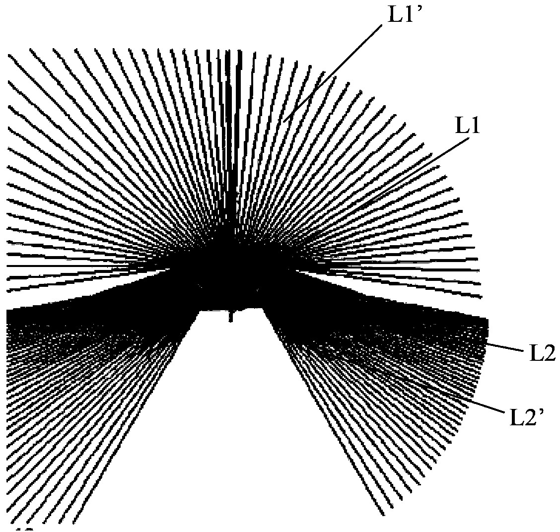
[0030] combine figure 2 , figure 2 is an optical path diagram of the lens 100 according to an embodiment of the present inventio...


PUM


Abstract

The present invention relates to a lens for a light source, comprising a bottom surface defining a recessed region at its center and a top surface rising from the bottom surface, wherein a surface of the recessed region comprises an incident surface disposed at its center and a reflective surface disposed around the incident surface, first incident light from the light source reaches and exits the top surface in a first direction after being refracted by the incident surface to form a first emergent light for forward illumination, and second incident light from the light source is reflected, when being emitted to the reflective surface, and then exits in a second direction to form a second emergent light for backward illumination. The present invention further relates to an illuminating device using the lens.

Description

technical field [0001] The present invention relates to a lens for a lighting device and a lighting device having the lens. Background technique [0002] Solid-state lighting (SSL) devices use light-emitting diodes (LEDs) and are rapidly evolving to gradually replace traditional ones such as incandescent and fluorescent lamps. LED has the advantages of low energy and high efficiency, long service life and compact design, which makes LED devices can replace traditional lighting devices in many occasions. In order to realize the effect of omnidirectional lighting on the basis of LED technology, the prior art provides various ways of improvement. [0003] In one prior art, refer to patent EP2180234A1, which provides an omnidirectional lighting bulb, which includes a transparent main body and a contact at one end of the main body. In addition, the light bulb also has a disk and a support column arranged in the bulb, and a plurality of LEDs are arranged on the circumference of ...

Claims


Application Information

Patent Timeline
IPC IPC(8): F21V5/04F21Y101/02
CPCG02B19/0061G02B19/0028F21V13/04G02B27/09F21K9/135F21K9/232F21K9/60F21V5/04F21V7/0091F21Y2101/00F21V29/74F21Y2115/10G02B19/0071
Inventor 林雪琴
Owner OSRAM GMBH
Why Eureka
Try Eureka