

Method for calibrating a position of a matrix headlamp of a motor vehicle, control device, and motor vehicle
A control device, technology for motor vehicles, used in testing the alignment of car headlights, headlights, measuring devices, etc.
- Summary
- Abstract
- Description
- Claims
- Application Information
AI Technical Summary
Problems solved by technology
Method used
Image

Examples
Embodiment Construction
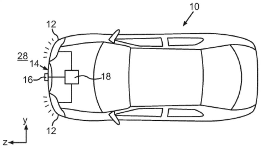
[0041] figure 1 A schematic illustration of a motor vehicle 10 according to an exemplary embodiment of the invention is shown, which has two array headlights 12 designed as headlights, a front camera 16 arranged on the vehicle front 14 and a control device 18 . In this case, the control device 18 is coupled not only to the camera 16 but also to the corresponding headlight array 12 and is designed to adjust the position of the headlight array 12 relative to the camera 16 . In this case, the adjustment of the right and left array headlights 12 takes place in the same manner and is therefore explained below only with reference to the individual array headlights 12 .
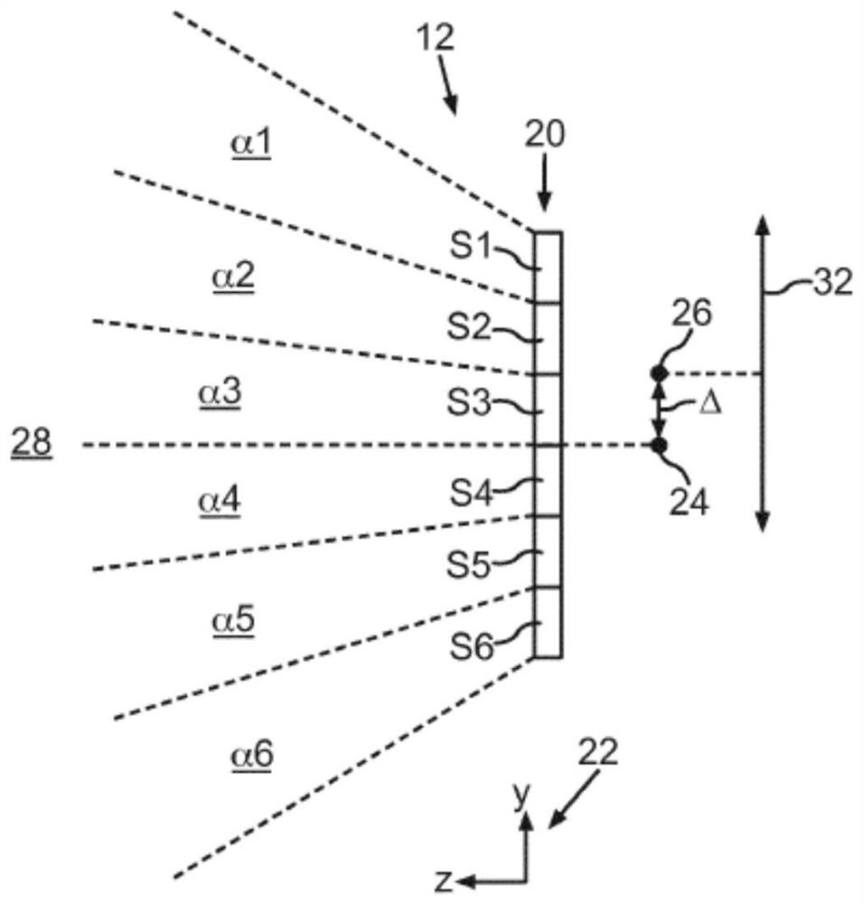
[0042] Such an array headlamp 12 is schematically shown again in detail in figure 2 shown in . The array headlight 12 here has, for example, six segments S1 , S2 , S3 , S4 , S5 , S6 arranged in a row 20 extending along the y-axis of the illustrated motor vehicle coordinate system 22 , Wherein, the corresponding...
PUM
 Abstract
Description
Claims
Application Information