Electronic equipment provided with display portion

a technology of electronic equipment and display portion, which is applied in the direction of identification means, instruments, lighting and heating apparatus, etc., can solve the problems of unavoidable parts cost rise and increase in assembly man-hour, and achieve the effect of reducing the number of leds, reducing the effect of spot light effect, and high transmissibility

Active Publication Date: 2012-09-13
ORMON CORP
View PDF0 Cites 1 Cited by
  • Summary
  • Abstract
  • Description
  • Claims
  • Application Information

AI Technical Summary

Benefits of technology

[0033]In this invention configured as above, the light beam of the LED mounted on the outer peripheral portion of the LCD indicator control substrate is caused to enter from the side of the side wall surface portion of the light guide plate, and then is guided to the side of the light guide surface portion of the light guide plate facing the diffusion sheet and led to the side of the LCD indicator, to radiate the display portion. As a result, the reaching radiation distance of the light beam emitted by the LED to the display portion is extended, so that the spot light effect is reduced. Thus, the thin diffusion sheet having high transmissibility with the advantage in terms of the cost can be adopted. Therefore, this invention can reduce the number of the LEDs to be used by using LEDs having a high brightness with a high light intensity, and as a result, the downsizing of the entire device is achieved, and further the assembly time is consequently reduced.

Problems solved by technology

However, such a backlight module requires an electric connection, such as made by thermo-compression and soldering of a flexible substrate, a mount pin, and the like for providing an electric interface, and an increase in assembling man-hour and a rise in the cost of parts are unavoidable.

Method used


Image

  • Electronic equipment provided with display portion
  • Electronic equipment provided with display portion
  • Electronic equipment provided with display portion

Examples


Embodiment Construction

[0041]An embodiment of this invention is configured so as to achieve an increase in an average light amount radiated to an LCD indicator by LEDs and reduction of a spot light effect at the same time while also sufficiently responding to a demand for downsizing.

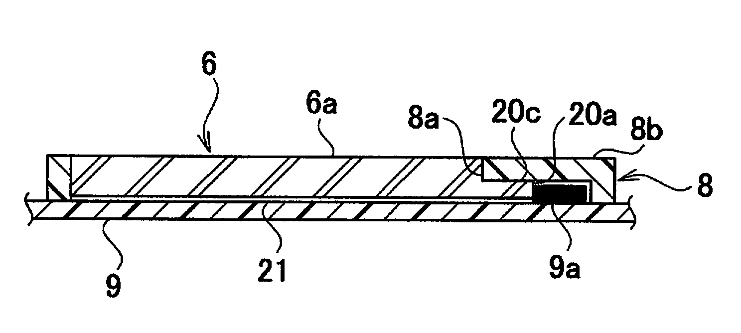
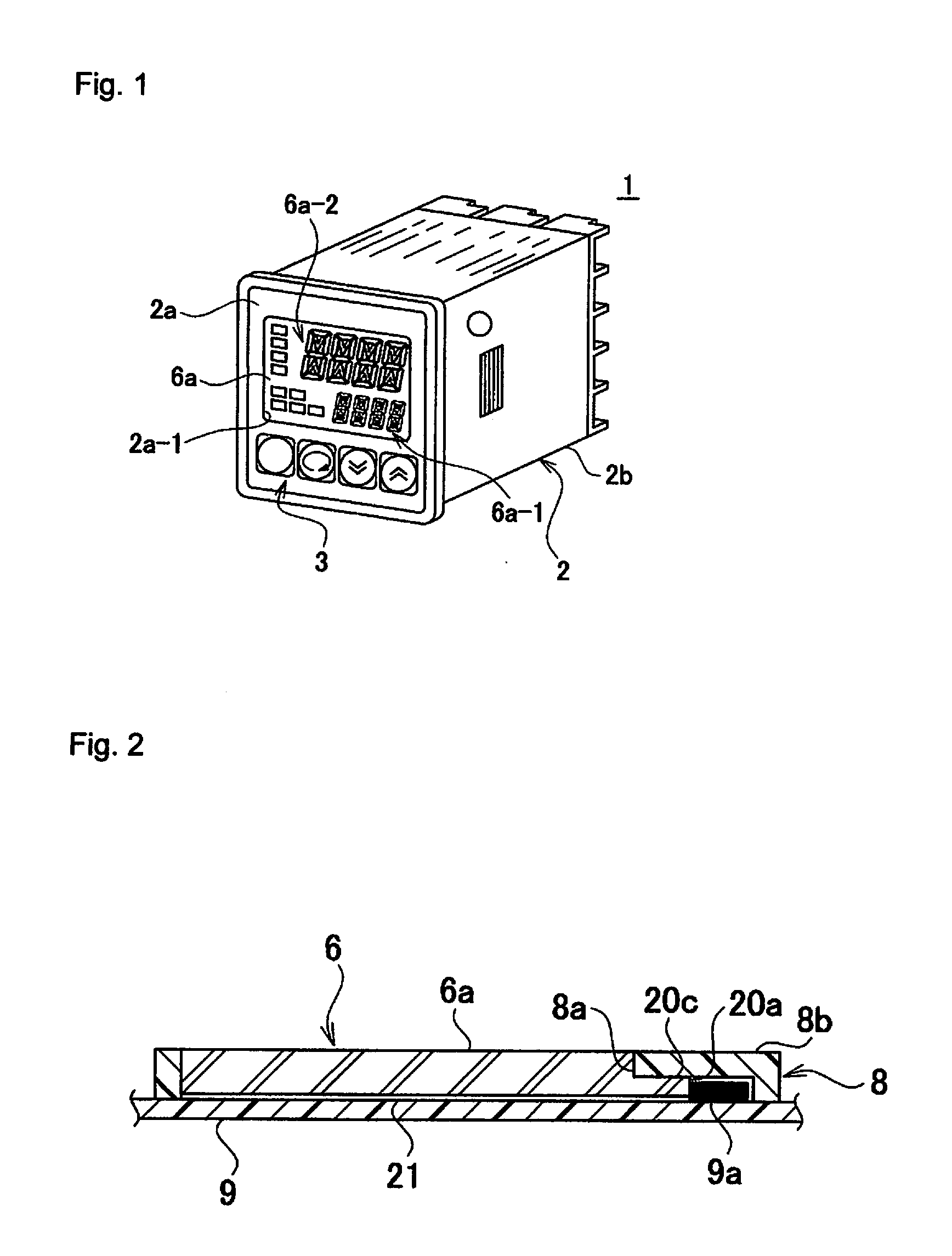
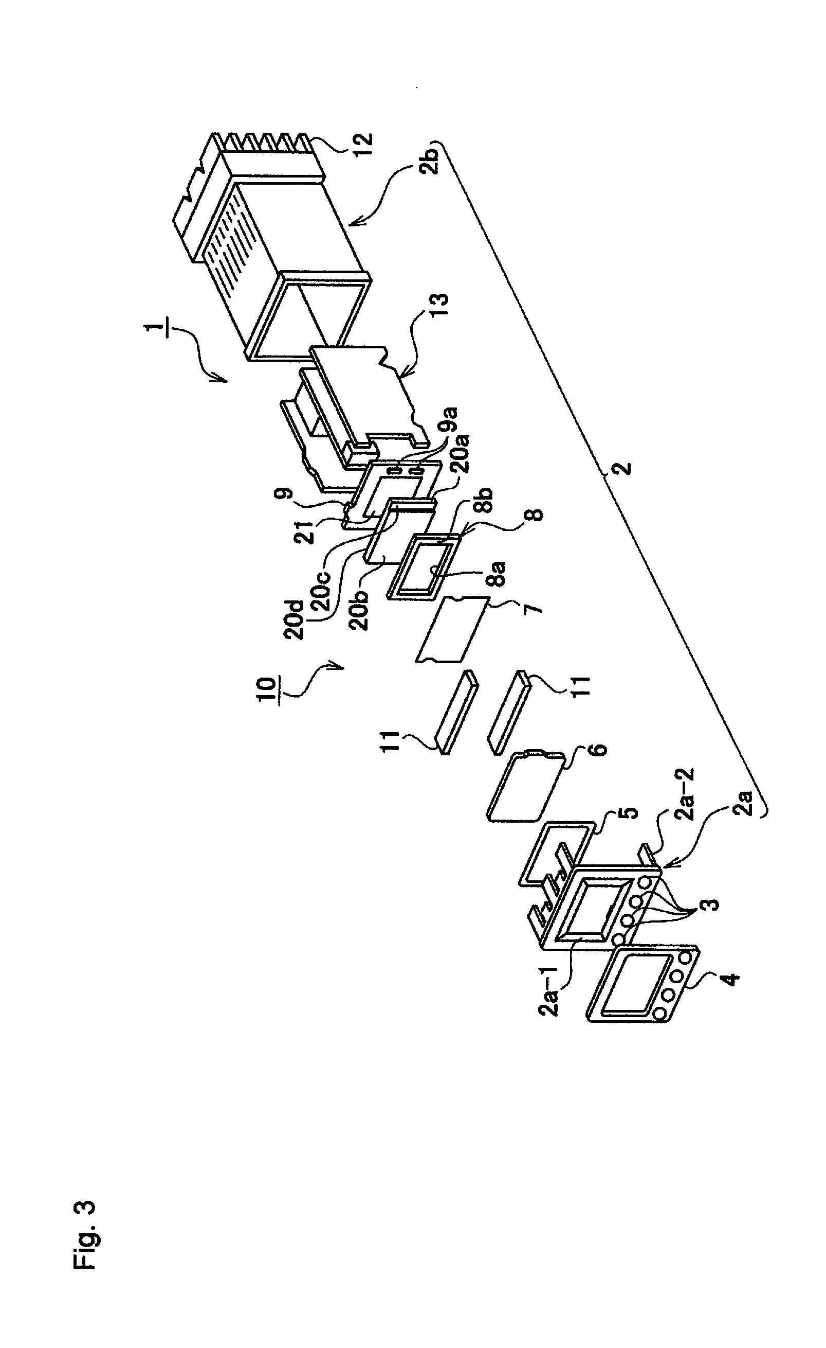
[0042]Next, one embodiment according to the present invention will be described with reference to the drawings, where configurations corresponding to the above conventional art will be given the same symbols. Firstly, an outer appearance configuration of a general temperature controller will be described with reference to FIG. 1. In a temperature controller 1 serving as an electronic equipment, a display region portion 6a serving as a display portion for displaying a set temperature value and the like, or a plurality of operation buttons 3 for operating a control unit and the like is disposed in a front surface portion of an electronic equipment casing 2, and an LCD indicator unit 10 and the like, described later, are accommod...


PUM


Abstract

An LCD indicator unit contains an LCD indicator with a display portion that includes set temperature and current temperature display portions, a diffusion sheet disposed on the rear surface side of the LCD indicator, a reflective frame body disposed on the rear surface side of the diffusion sheet, a light guide plate disposed on the rear surface side of the reflective frame body such that an outer peripheral portion thereof is covered with the reflective frame body, and an LCD indicator control substrate disposed on the rear surface side of the light guide plate, with LEDs serving as light sources for the LCD indicator mounted on a right-side outer peripheral portion on the front surface side of the LCD indicator control substrate. Light emitted from the LEDs is caused to enter a side wall surface portion of the light guide plate to irradiate the display portion of the LCD indicator.

Description

TECHNICAL FIELD[0001]The present invention relates to electronic equipment provided with a display portion such as a temperature controller, a timer, or a digital panel meter.BACKGROUND ART[0002]One type of electronic equipment is, for example, a temperature controller where the temperature of an item, serving as the object of the temperature control, is controlled by turning ON or OFF the power source of a heater used for heating the object of the temperature control. The heating is performed in relation to a predetermined control temperature set for the object of the temperature control.[0003]Such a temperature controller is configured using a plurality of electronic components installed and used in a control panel or the like on the side of an external device. The temperature controller accommodates a control board configuring a control unit for controlling the external device, a terminal to be electrically connected to the external device, and the like in an electronic equipment...

Claims


Application Information

Patent Timeline
Patent Type & Authority Applications(United States)
IPC IPC(8): G09F13/04
CPCG09F9/35G09F23/0058G09F2013/222G02F1/133308G02B6/0081G02F1/133615G02B6/0036G02B6/0061G02F1/133603
Inventor WAKABAYASHI, TAKESHIISHIDA, KAZUTO
Owner ORMON CORP
Why Eureka
Try Eureka