Battery monitoring device and a battery unit
A technology for battery monitoring and control components, which is applied to battery circuit devices, circuit devices, batteries, etc., and can solve problems such as abnormal communication and uncertainty
- Summary
- Abstract
- Description
- Claims
- Application Information
AI Technical Summary
Problems solved by technology
Method used
Image

Examples
no. 1 example
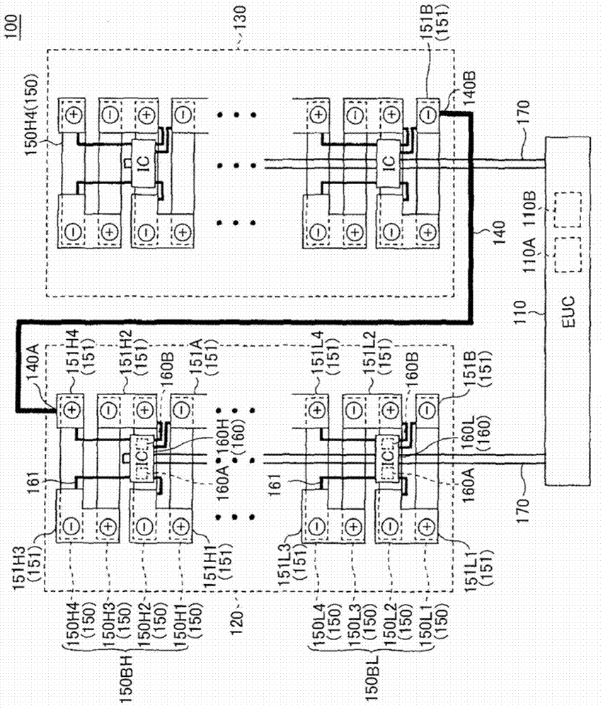
[0035] figure 1 is a diagram showing the battery monitoring device and battery components in the first embodiment.
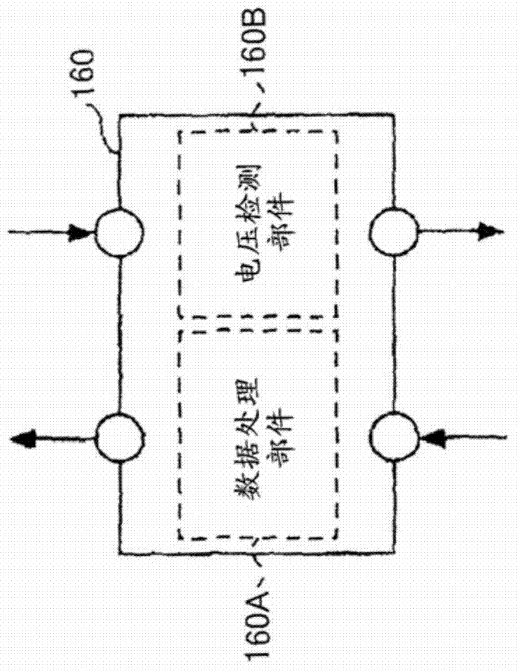
[0036] Main elements of the battery unit 100 in the first embodiment include an electronic control unit (ECU) 110 and battery stacks 120 and 130 . The battery stacks 120 and 130 each include a plurality of battery cells 150 and an integrated circuit (IC) chip 160 . The battery monitoring device in the first embodiment includes the ECU 110 and the IC chip 160 included in the battery stacks 120 and 130 .
[0037] figure 1 One example of the arrangement of the battery component 100 is schematically shown in plan view. The arrangement of ECU 110 and battery stacks 120 and 130 is not limited to figure 1 The pattern shown in, but may be another pattern arrangement.
[0038] The battery unit 100 is a device used as a power source of a driving device that outputs electric power to drive an electric vehicle. Here, the drive device of the electric vehicle refers to ...
no. 2 example
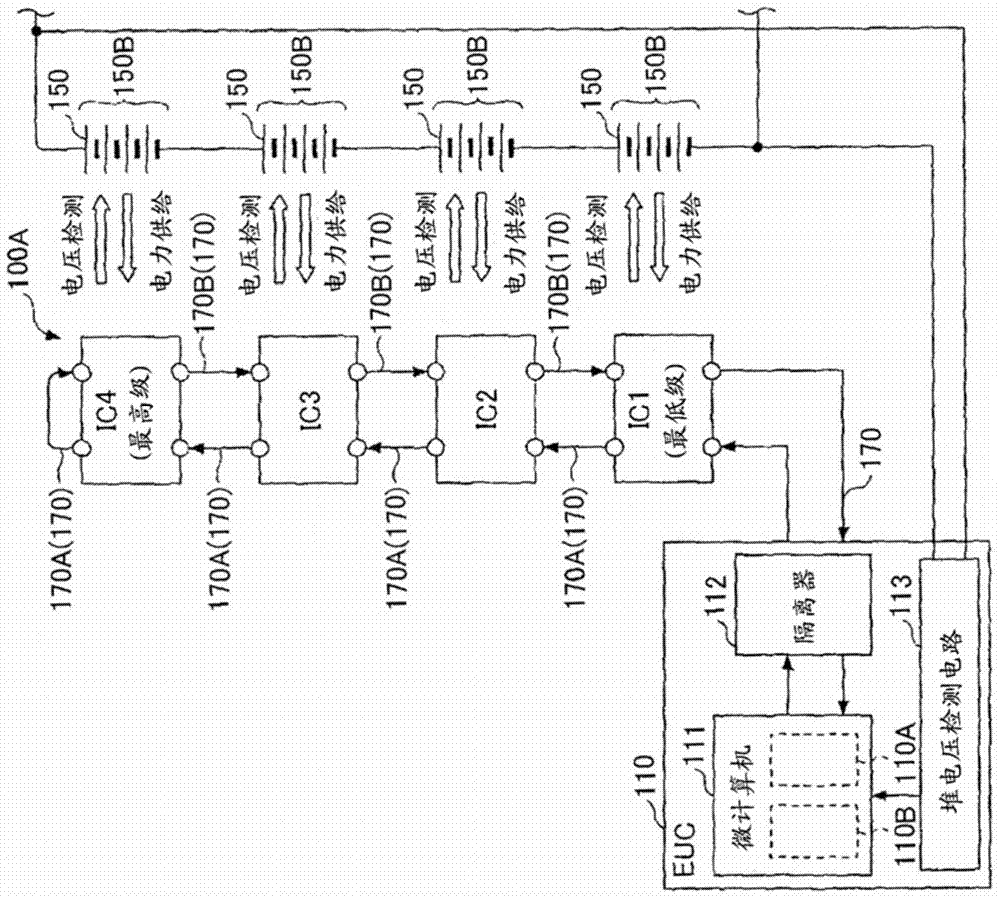
[0220] Figure 9 is a diagram showing the communication circuit 200 of the battery monitoring device in the second embodiment. The difference between the battery monitoring device in the second embodiment and the battery monitoring device 100A in the first embodiment is that it is used to determine on which signal line, that is, on the forward path signal line 170A or the backward path signal line 170B The method for determining a disconnected connection. Since other configurations are similar to those of the battery monitoring device 100A (see FIG. 2 ) in the first embodiment, the same reference numerals are given to the same elements and detailed descriptions are omitted.
[0221] The communication circuit 200 is inserted between the signal lines 170A and 170B between IC1 and IC2 shown in FIG. 2 . Communication circuit 200 is also inserted between IC2 and IC3 and between IC3 and IC4 between signal lines 170A and 170B. Both the signal lines 170A and 170B are used to transm...
no. 3 example
[0240] FIG. 10 is a diagram showing a battery monitoring device 300A in the third embodiment. Figure 10A A battery monitoring device 300A in the third embodiment shown in has a configuration similar to that of the battery monitoring device 100A in the first embodiment except that the stack voltage detection circuit 113 is removed from the battery monitoring device 100A and the capacitor 311 is added to ECU310. Since other configurations are similar to those of the battery monitoring device 100A in the first embodiment, the same reference numerals are given to the same elements and detailed descriptions are omitted.
[0241] ECU 310 includes microcomputer 111 , isolator 112 and capacitor 311 . One end of the capacitor 311 is connected to the point where the forward path signal line 170A turns around at IC4 through the signal line 320 , and the other end is connected to the microcomputer 111 . That is, the signal line 320 connects the ECU 310 to the IC 4 which is the farthest...
PUM
 Abstract
Description
Claims
Application Information
 - R&D Engineer
- R&D Manager
- IP Professional
- Industry Leading Data Capabilities
- Powerful AI technology
- Patent DNA Extraction
Browse by: Latest US Patents, China's latest patents, Technical Efficacy Thesaurus, Application Domain, Technology Topic.
© 2024 PatSnap. All rights reserved.Legal|Privacy policy|Modern Slavery Act Transparency Statement|Sitemap