Optical network system and network function visualizing method

An optical network and network technology, which is applied in the field of systems for realizing network function virtualization of traditional optical network equipment, can solve the problem of data optical network being difficult to handle, and achieve the effect of realizing network virtualization function and improving network virtualization function.

Inactive Publication Date: 2015-01-21
中国电力科学研究院信息通信研究所 +1
View PDF4 Cites 21 Cited by
  • Summary
  • Abstract
  • Description
  • Claims
  • Application Information

AI Technical Summary

Problems solved by technology

[0006] In order to solve the problem that data is difficult to be processed when it is mapped to an optical network, the present invention proposes a method for realizing network function virtualization and a corresponding optical network system based on the NFV characteristic node architecture

Method used


Image

  • Optical network system and network function visualizing method
  • Optical network system and network function visualizing method
  • Optical network system and network function visualizing method

Examples


Embodiment Construction

[0023] The embodiments of the present invention will be described in further detail below in conjunction with the accompanying drawings.

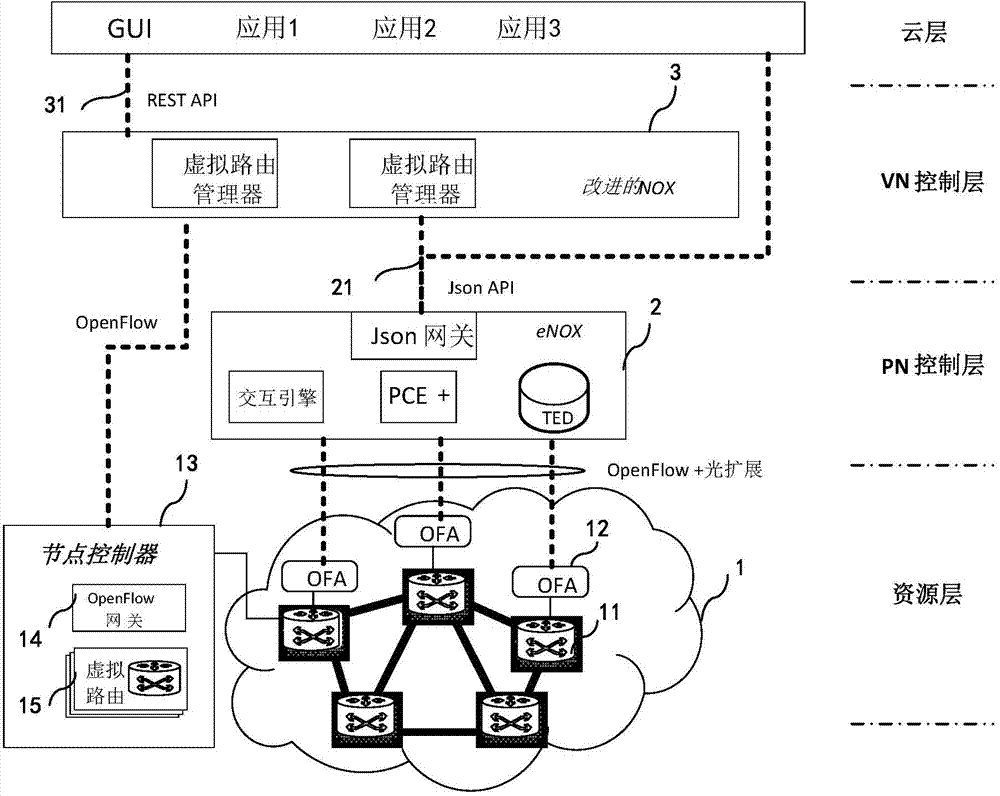
[0024] figure 2 Indicates the optical network system architecture supporting NFV optical network nodes. It is divided into four layers, including resource layer, physical network (PN) control layer, virtual network (VN) control layer and cloud layer. figure 2 The modified NOX described in is an extended NOX to the standard, which is the heart of the controller. With the continuous access to the representation of resources, the client application is constantly changing its state, which is called Representational State Transfer (REST, Representational State Transfer); OFA is the OpenFlow agent; eNOX is NOX with improved performance.

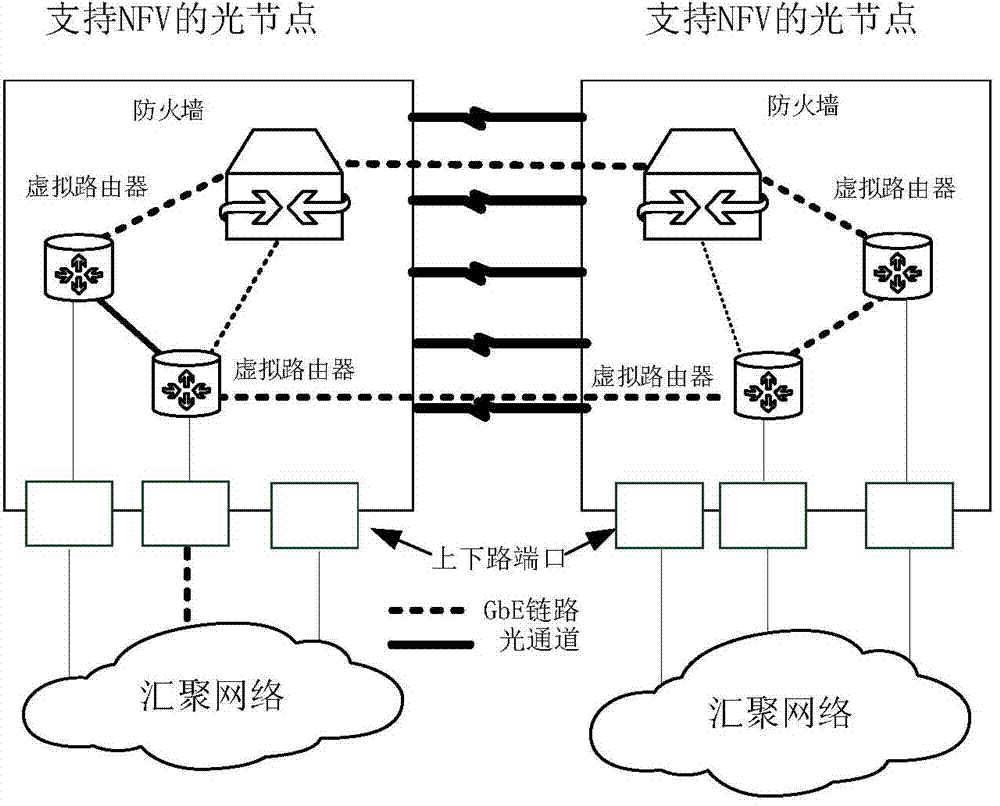
[0025] The resource layer includes all network hardware facilities 1 . Optical nodes 11 supporting NFV are placed at this layer. Node resources are abstracted with the OpenFlow Protocol (OFP) with optical ...


PUM


Abstract

The invention provides a method for achieving network function visualization and a corresponding optical network system based on NFV character node architecture to solve the problem that it is difficult to handle data when the data are mapped to the optical network. The system comprises a resource layer, a physical network control layer, a virtual network control layer and a cloud layer. The network function visualizing method comprises the steps that the cloud layer proposes a virtual network establishing request for the virtual network control layer, the virtual network control layer selects the geographic position of a virtual network node and a source node of an optical channel, the physical network control layer carries out routing selecting and wavelength allocating according to the current node link resource situation to establish virtual network nodes, and the virtual network control layer establishes connection with all the virtual network nodes through the OpenFlow protocol. The novel optical network architecture is adopted, and therefore the data of the optical network in a traditional OTN device can be processed, and the network visualization function can be achieved very well.

Description

technical field [0001] The invention is a system method for realizing network function virtualization of traditional optical network equipment, and in particular relates to the node structure under the network function virtualization framework in the optical network and software-defined optical network technology. Background technique [0002] With the continuous opening of network resource acquisition and the rise of network applications, network hardware devices with various functions are required as communication infrastructure. Network providers need to replace old equipment with new equipment to support new network applications, which will bring huge energy and capital investment. Network Functions Virtualization (NFV) technology aims to solve these problems by integrating various network devices into industry-standard components. [0003] The main barriers to the realization of NFV are the network bandwidth supporting network function virtualization and the number of ...

Claims


Application Information

Patent Timeline
Patent Type & Authority Applications(China)
IPC IPC(8): H04Q11/00
Inventor 汪洋李新胡紫薇丁慧霞高强赵永利王强张杰杨辉
Owner 中国电力科学研究院信息通信研究所
Why Eureka
Try Eureka