Piezoelectric pump and blood-pressure-information measurement device provided therewith

A technology of piezoelectric pumps and piezoelectric elements, applied to pumps with flexible working elements, pumps, blood vessel evaluation, etc., can solve problems such as difficult results, leakage, and insufficient pressurization, and achieve good pressurization efficiency

Active Publication Date: 2015-01-21
OMRON HEALTHCARE CO LTD
View PDF5 Cites 65 Cited by
  • Summary
  • Abstract
  • Description
  • Claims
  • Application Information

AI Technical Summary

Problems solved by technology

[0011] However, the piezoelectric pump with the above-mentioned structure has the following problem: when the driver is displaced toward the side where the diaphragm is located (that is, when the pump chamber performs a discharge action), a part of the fluid in the pump chamber is directed toward the suction side through the communication hole provided on the diaphragm. backflow (leakage)
[0012] Therefor...

Method used


Image

  • Piezoelectric pump and blood-pressure-information measurement device provided therewith
  • Piezoelectric pump and blood-pressure-information measurement device provided therewith
  • Piezoelectric pump and blood-pressure-information measurement device provided therewith

Examples


Embodiment approach 1

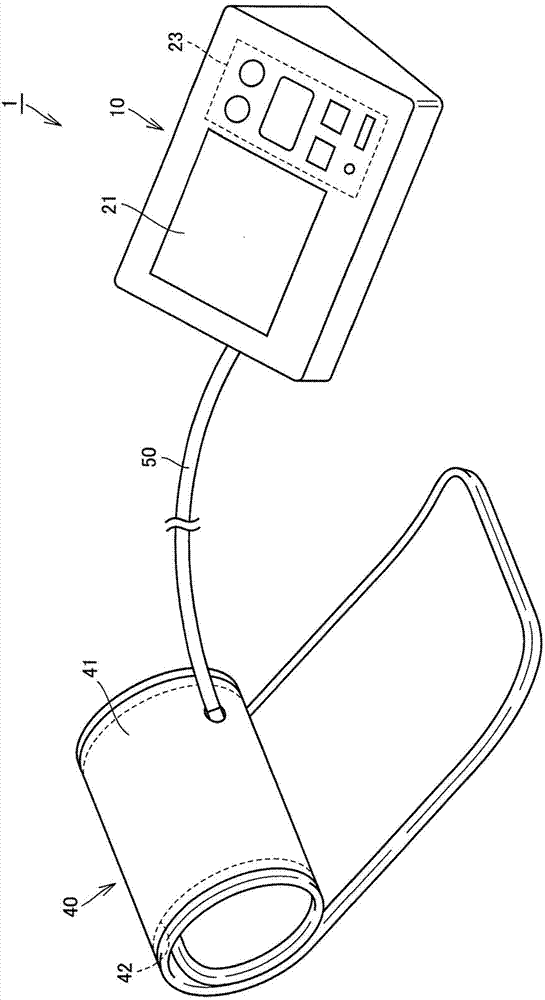
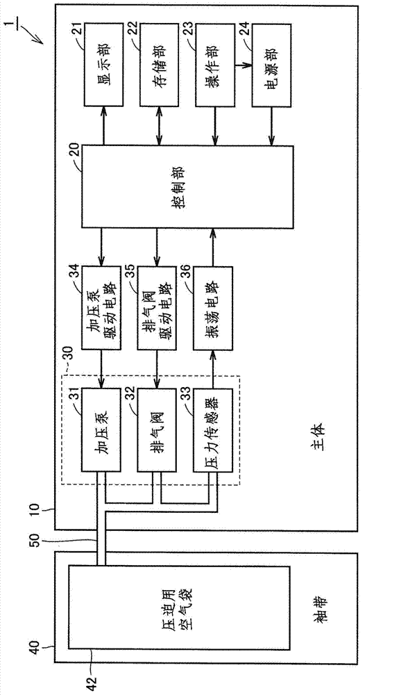
[0042] figure 1 It is a perspective view showing the appearance structure of the sphygmomanometer according to Embodiment 1 of the present invention, figure 2It is a diagram showing the functional block configuration of the sphygmomanometer of the present embodiment. First, refer to the above figure 1 with figure 2 , the structure of the sphygmomanometer 1 of this embodiment will be described.

[0043] Such as figure 1 As shown, the sphygmomanometer 1 of this embodiment includes a main body 10 , a cuff 40 and an air tube 50 . The main body 10 has a box-shaped frame, and has a display unit 21 and an operation unit 23 on the upper surface of the main body 10 . The main body 10 is used by being placed on a mounting surface such as a desk during measurement. The cuff 40 has a generally annular shape as a whole, and mainly includes a belt-shaped bag-shaped outer cover 41 and a compression air bag 42 as a compressive fluid bag built in the outer cover 41 . The cuff 40 is us...

Embodiment approach 2

[0100] Figure 9 is a schematic cross-sectional view of a piezoelectric pump according to Embodiment 2 of the present invention, Figure 10 It is a perspective view of the first diaphragm of the piezoelectric pump of this embodiment. First, refer to the above Figure 9 with Figure 10 , the structure of the piezoelectric pump 100B of this embodiment will be described. In addition, the piezoelectric pump 100B of the present embodiment is also used as the pressurizing pump 31 for pressurizing the compression air bladder 42 in the sphygmomanometer 1 as in the case of the above-described first embodiment.

[0101] Such as Figure 9 As shown, when the piezoelectric pump 100B is compared with the piezoelectric pump 100A of the first embodiment, the difference is that the piezoelectric pump 100B does not include the second diaphragm 150 and has a film-shaped valve body as the backflow suppressing portion. 142A instead of the opposing wall portion 151 provided on the second diaph...


PUM

PropertyMeasurementUnit
Thicknessaaaaaaaaaa
Thicknessaaaaaaaaaa
Thicknessaaaaaaaaaa

Abstract

A piezoelectric pump (100A) is provided with the following: an actuator (130) containing a piezoelectric element (134) and a vibrating sheet (131); a first diaphragm (140), positioned opposite the actuator (130), with a first connecting hole (141) provided therein; a pump chamber (192) comprising the space between the actuator (130) and the first diaphragm (140); and a second diaphragm (150) positioned opposite the first diaphragm (140). The part of the second diaphragm (150) opposite the first connecting hole (141) is provided with an opposing wall part (151) that prevents a fluid that has been introduced into the pump chamber (192) via the first connecting hole (141) from flowing back towards an intake side via the first connecting hole (141).

Description

technical field [0001] The present invention relates to a piezoelectric pump that sucks in a fluid and discharges the fluid by using a piezoelectric element, and a blood pressure information measuring device having the piezoelectric pump as a pressure fluid bag for compressing the piezoelectric pump. Pressurized booster pump. Background technique [0002] Measuring the subject's blood pressure information is very important in grasping the subject's health status. In recent years, for example, systolic blood pressure and diastolic blood pressure, whose role has been widely recognized, are representative indicators that contribute to the risk analysis of cardiovascular system diseases such as cerebrovascular diseases, cardiac insufficiency, and myocardial infarction, but are not limited to the measurement of systolic blood pressure, diastolic blood pressure, and blood pressure. It is also attempted to detect heart load, arteriosclerosis, etc. by measuring the subject's pulse ...

Claims


Application Information

Patent Timeline
IPC IPC(8): F04B45/047A61B5/022
CPCA61B5/02141F04B43/046A61B5/02225A61B5/02233A61B5/0225A61B5/0235
Inventor 佐野佳彦小椋敏彦小林达矢山下佑辉土居由树角田亘
Owner OMRON HEALTHCARE CO LTD
Why Eureka
Try Eureka